Cascade Bridge-type DC-AC Power Conversion Method and Converter Device Thereof

a converter device and cascade bridge technology, applied in the direction of dc-ac conversion without reversal, power conversion systems, electrical equipment, etc., can solve the problems of unavoidable defect topology of the conventional cascade bridge-type dc-ac converter device, power loss, and power loss, so as to reduce the capacity of filters and reduce switching power loss. , the effect of reducing the power loss in filters

Active Publication Date: 2014-10-09
ABLEREX ELECTRONICS CO LTD
View PDF4 Cites 17 Cited by
  • Summary
  • Abstract
  • Description
  • Claims
  • Application Information

AI Technical Summary

Benefits of technology

[0010]The primary objective of this invention is to provide a cascade bridge-type DC-AC power conversion method and converter device thereof. The cascade bridge-type DC-AC power converter device connects between a DC power source circuit and a distribution power system. The cascade bridge-type DC-AC power converter device is operated to convert an electric power supplied from the DC power source circuit into an AC power with a multi-level AC voltage which is injected into the distribution power system. Advantageously, the present invention is accordingly successful in reducing the switching power loss of the cascade bridge-type DC-AC power converter device, lowering the capacity of filters located at an output terminal of the cascade bridge-type DC-AC power converter device and reducing the power loss in the filters so as to increase the efficiency of power conversion, to reduce total dimensions and manufacturing cost.

Problems solved by technology

However, these power electronic switches do not have an ideal characteristic so that switching operation of the power electronic switches will cause power loss.
The switching power loss will reduce the efficiency of power conversion of the DC-AC converter device.
However, the topology of the conventional cascade bridge-type DC-AC power converter device has an unavoidable defect of adopting several DC sources which has no common point to connect to each DC bus of each bridge-type DC-AC power converter.
Accordingly, this results in a complicated circuit and an increase of manufacturing cost.
Furthermore, the power electronic switches of each bridge-type DC-AC power converter must be controlled by high-frequency PWM which further results in a complication of the driving circuit and a higher switching power loss.

Method used


Image

  • Cascade Bridge-type DC-AC Power Conversion Method and Converter Device Thereof
  • Cascade Bridge-type DC-AC Power Conversion Method and Converter Device Thereof
  • Cascade Bridge-type DC-AC Power Conversion Method and Converter Device Thereof

Examples


first embodiment

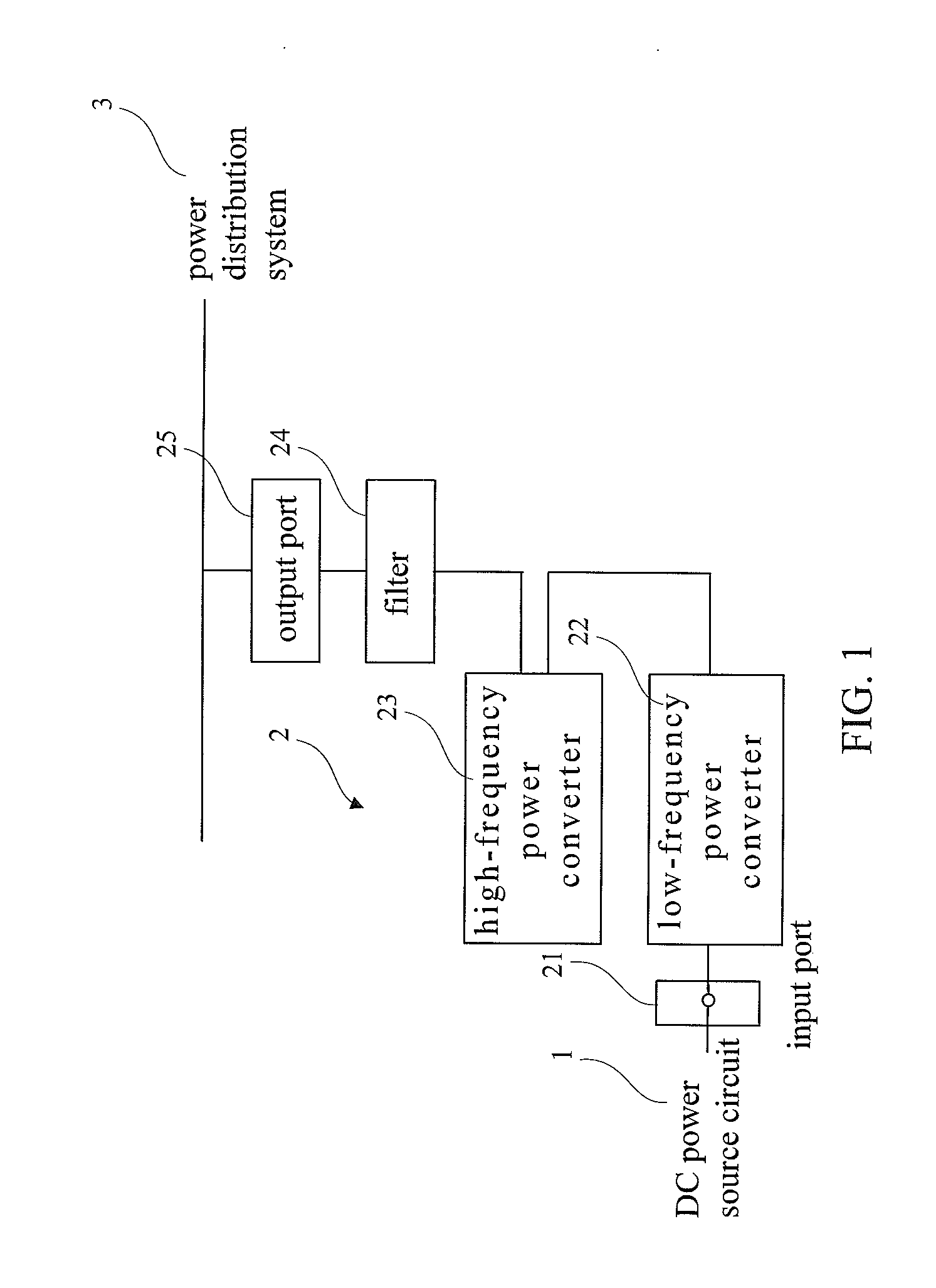
[0057]FIG. 3 shows the cascade bridge-type DC-AC power converter device in accordance with a first preferred embodiment of the present invention which corresponds to the cascade bridge-type DC-AC power converter device 2 in FIG. 1. Referring now to FIGS. 1 and 3, in the first embodiment, the DC input port 21 of the cascade bridge-type DC-AC power converter device 2 connects to the DC power source circuit 1 while the AC output port 25 of the cascade bridge-type DC-AC power converter device 2 connects to a single-phase distribution power system 3′. The low-frequency bridge-type power converter 22 and the high-frequency bridge-type power converter 23 are selected from a single-phase full-bridge power converter. The second DC bus of the high-frequency bridge-type power converter 23 only connects to a capacitor which is performed as a power buffer. Furthermore, a voltage of the second DC bus of the high-frequency bridge-type power converter 23 is higher than or equals a half voltage of t...

second embodiment

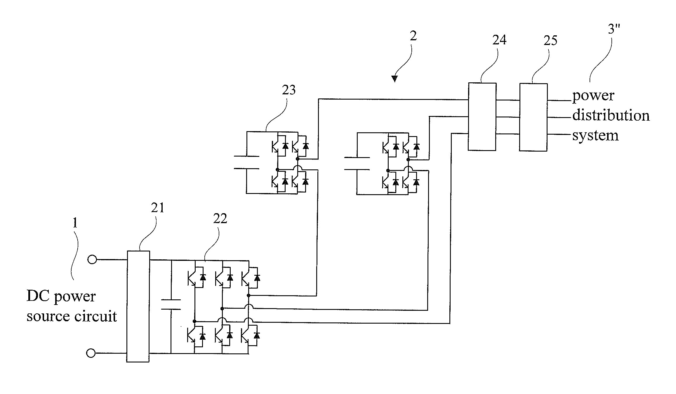
[0059]FIG. 4A shows the cascade bridge-type DC-AC power converter device in accordance with a second preferred embodiment of the present invention which corresponds to the cascade bridge-type DC-AC power converter device 2 in FIG. 1. Referring now to FIGS. 1 and 4A, in the second embodiment, the DC input port 21 of the cascade bridge-type DC-AC power converter device 2 connects to the DC power source circuit 1 while the AC output port 25 of the cascade bridge-type DC-AC power converter device 2 connects to a three-phase three-wire distribution power system 3″. The low-frequency bridge-type power converter 22 is selected from a three-phase bridge-type power converter and the high-frequency bridge-type power converter 23 includes two single-phase full-bridge power converters. The second DC buses of the two single-phase full-bridge power converters of the high-frequency bridge-type power converter 23 only connect to capacitors which are performed as power buffers. Furthermore, the volt...

third embodiment

[0061]FIG. 4B shows the cascade bridge-type DC-AC power converter device in accordance with a third preferred embodiment of the present invention which is similar to the cascade bridge-type DC-AC power converter device 2 in FIG. 4A. Referring now to FIGS. 1 and 4B, in the third embodiment, the DC input port 21 of the cascade bridge-type DC-AC power converter device 2 connects to the DC power source circuit 1 while the AC out port 25 of the cascade bridge-type DC-AC power converter device 2 connects to the three-phase three-wire distribution power system 3″. The low-frequency bridge-type power converter 22 is selected from the three-phase bridge-type power converter and the high-frequency bridge-type power converter 23 includes three single-phase full-bridge power converters. The second DC buses of the three single-phase full-bridge power converters of the high-frequency bridge-type power converter 23 only connect to capacitors which are performed as power buffers.


PUM


Abstract

A cascade bridge-type DC-AC power converter device includes a low-frequency bridge-type power converter including an AC terminal and a DC bus and a high-frequency bridge-type power converter including an AC terminal. A power conversion method includes: serially connecting the AC terminal of the high-frequency bridge-type power converter and the AC terminal of the low-frequency bridge-type power converter; operating frequency of the low-frequency bridge-type power converter synchronized with frequency of an AC source and operating the high-frequency bridge-type power converter with high-frequency PWM to generate a multilevel AC voltage. A DC power source connects to the DC bus of the low-frequency bridge-type power converter. No additional power supply circuit will be required for power supply to a DC bus of the high-frequency bridge-type power converter. Accordingly, the power circuit is simplified and the manufacturing cost is reduced.

Description

BACKGROUND OF THE INVENTION[0001]1. Field of the Invention[0002]The present invention relates to a cascade bridge-type DC-AC power conversion method and converter device thereof. More particularly, the present invention relates to the cascade bridge-type DC-AC power conversion method and converter device thereof for enhancing the efficiency of power conversion.[0003]2. Description of the Related Art[0004]Recently, several new energy sources (i.e. solar energy, wind energy and fuel cells) have been widely developed in power generation to reduce relying on the power of fossil fuels, the effect of environment pollutions and global warming. Most power generation systems of the new energy sources connect parallel and supply to a power distribution network but, however, these new power generation systems supply DC power. These DC power generated from the new energy sources must be converted into AC power by a DC-AC power converter such that the power generation systems can high-quality AC...

Claims


Application Information

Patent Timeline
Patent Type & Authority Applications(United States)
IPC IPC(8): H02M7/5387
CPCH02M7/5387H02M7/49H02M5/08H02M5/14
Inventor WU, CHIN-CHANGCHIANG, WEN-JUNGHUANG, CHIEN-MINGHOU, WEN-JIE
Owner ABLEREX ELECTRONICS CO LTD
Why Eureka
Try Eureka