Eureka AIR delivers breakthrough ideas for toughest innovation challenges, trusted by R&D personnel around the world.

Non-Contiguous Carrier Aggregation

a non-contiguous carrier and carrier technology, applied in the field of non-contiguous carrier aggregation, can solve the problems of inability to assume the same power received in the wanted carrier, the inability to accept the interference signal of an interference, and the inability to accept the interference signal. the effect of reducing the complexity, reducing the cost, and improving the reliability of selection

Inactive Publication Date: 2014-10-09
TELEFON AB LM ERICSSON (PUBL)
View PDF2 Cites 14 Cited by
  • Summary
  • Abstract
  • Description
  • Claims
  • Application Information

AI Technical Summary

Benefits of technology

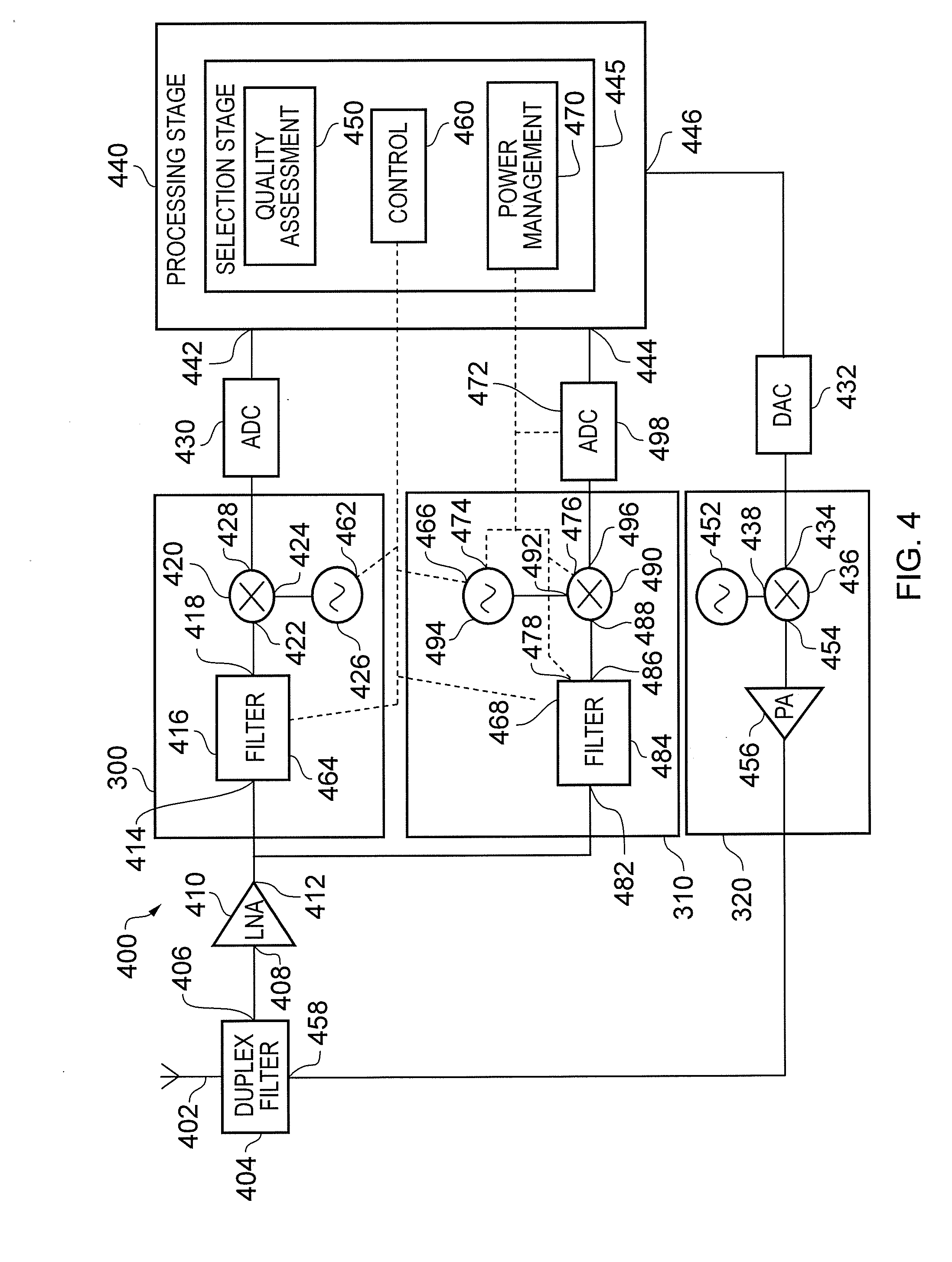
The patent text describes a wireless communication device that can switch between a single-receiver and dual-receiver architecture based on the device's performance needs. The single-receiver architecture provides a simple and low power consumption solution when its performance is sufficient, while the dual-receiver architecture offers better performance, especially a higher rejection of interferers. The device can switch between the two architectures based on the amount of interference it experiences. The selection stage can also inhibit power consumption to one of the mixers and oscillators when the single-receiver architecture is selected. Overall, this invention enables better performance with reduced power consumption.

Problems solved by technology

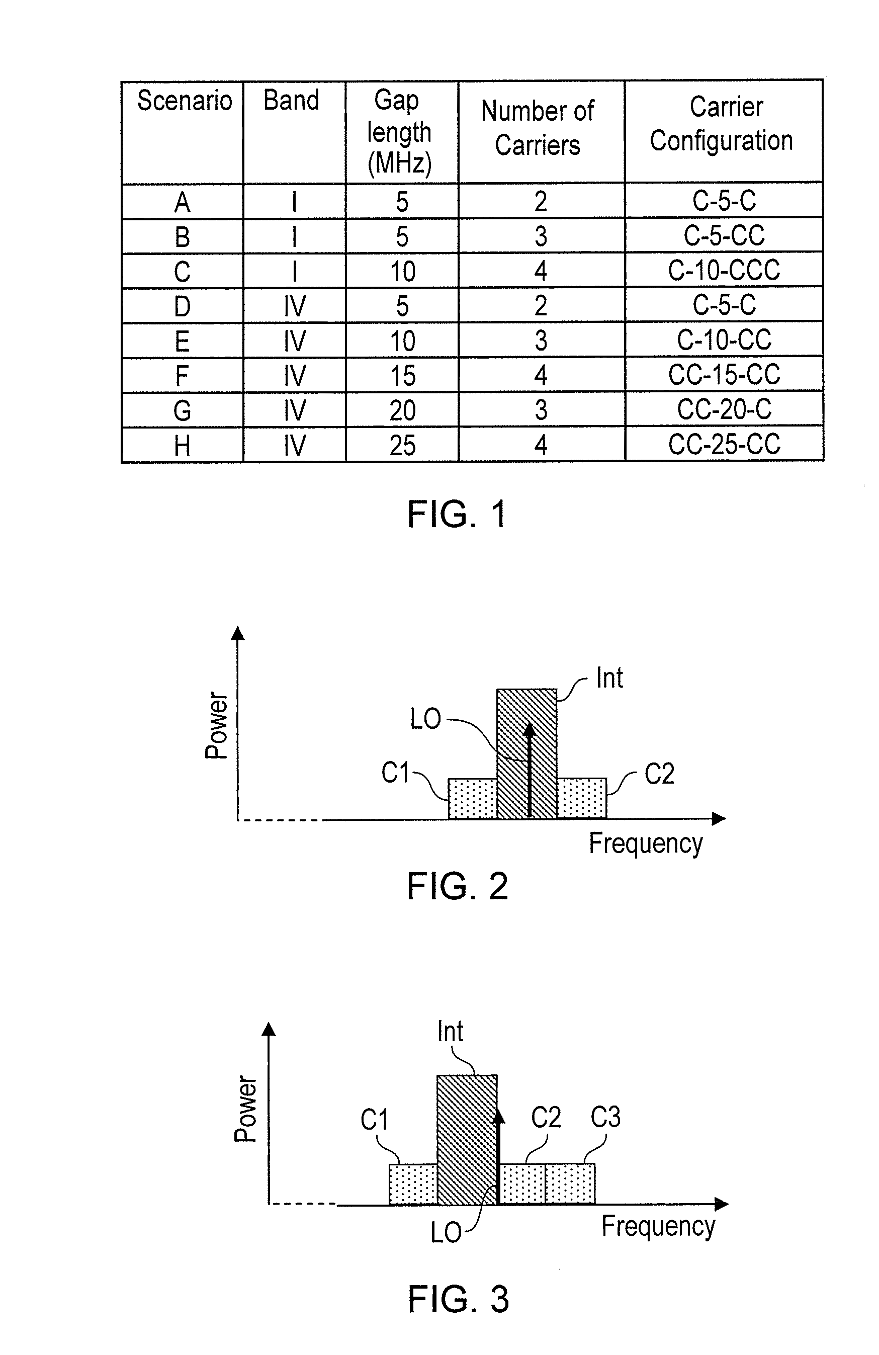
Such an unwanted carrier may therefore also be regarded as an interference signal.
Indeed, it is very likely that an interferer will be present in the gap.
Moreover, similar power received in the wanted carrier and in the gap cannot be assumed unless geographical co-location of the two operators is possible.
So, whereas systems employing carrier aggregation may control the relative levels of the contiguous carriers, with non-contiguous carriers, the level of an interference signal in a gap may not be controllable by the system and may be relatively high.
Such a receiver can be complex, large, and have relatively high power consumption, in comparison with a receiver arranged for receiving only contiguous carriers.
However, such a scheme can be slow, particularly where many candidate carriers are measured, or where the measurements takes place at intervals during time gaps in ongoing communication.

Method used


Image

  • Non-Contiguous Carrier Aggregation
  • Non-Contiguous Carrier Aggregation
  • Non-Contiguous Carrier Aggregation

Examples


example 1

[0070]In response to a request, received from a NodeB, for the UE to perform inter-frequency measurements on a certain set of carriers in order to schedule non-contiguous carrier aggregation, the UE, or wireless communication apparatus 400, performs the following steps:[0071]1. Using the single-receiver architecture, change the position of the single LO during a single measurement period or gap to the middle of configuration C1xC2C3;[0072]2. Compute RSSI and Ec / No for the three wanted carriers, RSSI1, RSSI2, RSSI3, where Ec is the energy of the wanted signal (by default calculated on a common pilot channel), No is noise-plus-interference, and RSSIj is received signal strength indicator for carrierj, j=1 . . . 3;[0073]3. Compute the RSSI in the gap, RSSIG;[0074]4. Compare RSSIG with RSSI1, RSSI2, RSSI3 as follows. If RSSIG >A*(RSSI1+RSSI2+RSSI3) / 3, where A is a predetermined threshold, (note that the equation is in linear domain), use the dual-receiver the single-receiver architectur...

example 2

[0077]In response to a request, received from a NodeB, for the UE to perform inter-frequency measurements on a certain set of carriers in order to schedule non-contiguous carrier aggregation, the UE performs the following steps:[0078]1. Using the single-receiver architecture, change the position of the single LO during a (single) measurement time period or gap to the middle of configuration C1xC2C3;[0079]2. Compute RSSI and Ec / No for the three wanted carriers, RSSI1, RSSI2, RSSI3, Ec / No1, Ec / No2 and Ec / No3, where Ec / Noj is the signal to noise-plus-interference ratio for carrierj, j=1 . . . 3;[0080]3. Compare RSSI1, RSSI2 and RSSI3 and Ec / No1, Ec / No2 and Ec / No3 as follows. Depending on the configuration, the UE knows a priori which carrier can be affected by the image problem; in this example this is C2. In general let's call Cimage the carrier which can be affected by the image problem and Cnoimage the set of carriers not affected by image problem, hence if RSSICimage>A*ECnoimage[RS...

example 3

[0085]If the signalling is not in place, that is, if the NodeB does not request the UE to perform the inter-frequency measurements before scheduling non-contiguous carrier aggregation, the UE can start supporting the scheduled non contiguous carrier aggregation configuration by using the dual-receiver architecture and operating in accordance with example 7 or 8 during the communication to reduce power consumption by optimizing its receiver when the interference level in the gap is below a certain threshold.


PUM


Abstract

A method of operating a wireless communication apparatus (400) comprises selecting, for non-contiguous carrier aggregation of a plurality of carriers, between a single-receiver architecture and a dual-receiver architecture, depending on a level of an interferer in a gap in the carriers.

Description

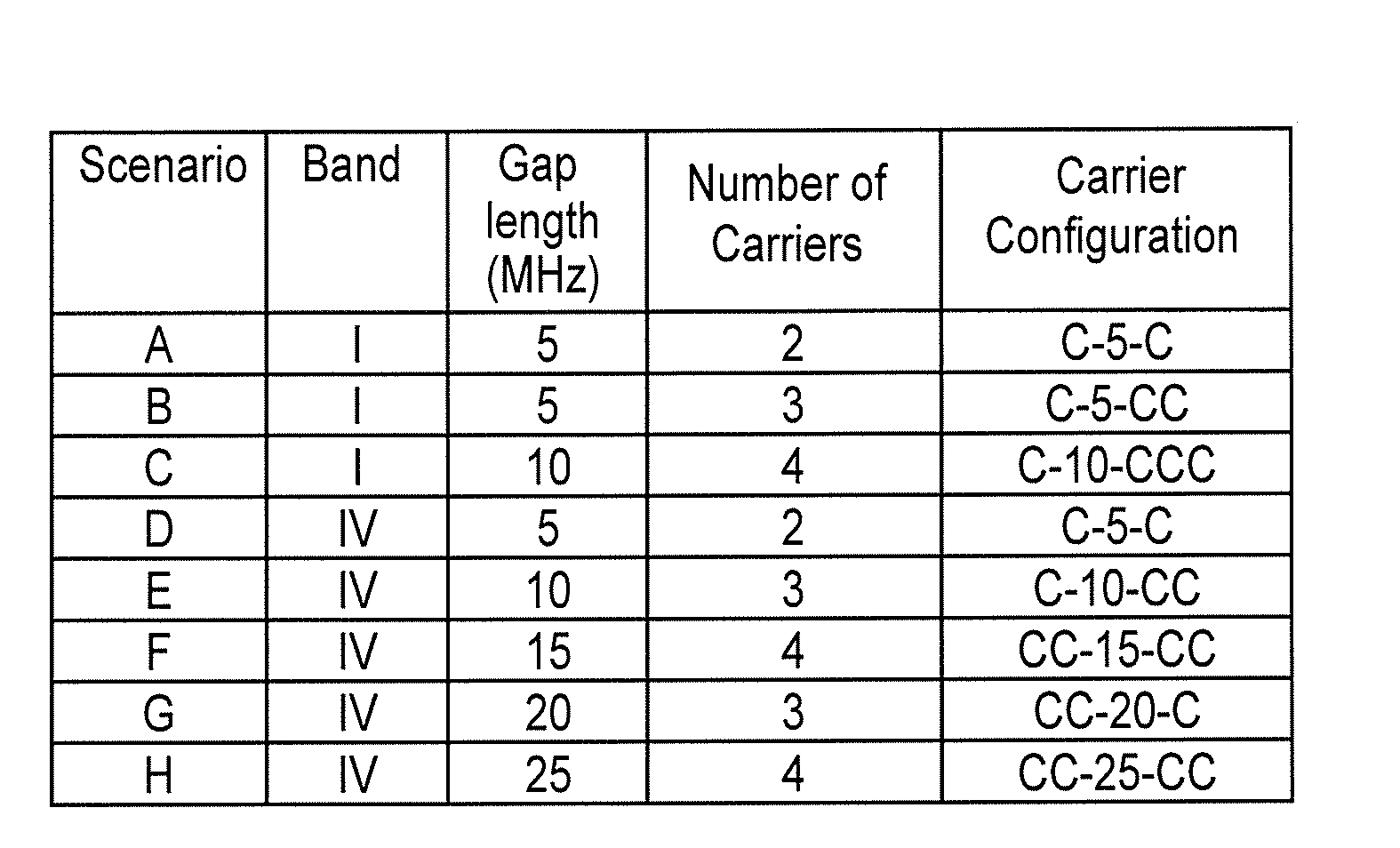
FIELD OF THE DISCLOSURE[0001]The present disclosure relates to methods and apparatus for carrier aggregation in the field of wireless communication, and in particular non-contiguous carrier aggregation. The disclosure has application, in particular but not exclusively, in wireless communication systems and apparatus adapted for operation in accordance with the Third Generation Partnership Project (3GPP) Long Term Evolution (LTE) protocol, such as a User Equipment.BACKGROUND TO THE DISCLOSURE[0002]Carrier aggregation is a technique available for increasing the bandwidth available for communication by employing simultaneously more than one carrier for communication by a single communication device. The carriers may be in different radio frequency bands, in which case they occupy portions of spectrum that are spaced apart, or may occupy contiguous portions of spectrum in a single radio frequency band, or a combination of both possibilities, occupying contiguous portions of different ra...

Claims


Application Information

Patent Timeline
Patent Type & Authority Applications(United States)
IPC IPC(8): H04B1/00
CPCH04B1/0067H04L5/001H04W52/0238H04W52/0245H04B1/0053H04L5/0041H04L27/2647H04W52/34H04W52/0206Y02D30/70
Inventor SESIA, STEFANIABRUNEL, DOMINIQUE
Owner TELEFON AB LM ERICSSON (PUBL)
Why Eureka
Eureka Blog
Learn More