Ultrasound diagnostic apparatus and method for controlling the same

a technology of ultrasound diagnostic apparatus and ultrasonic, applied in the field of ultrasonic diagnostic apparatus, can solve the problems of high degree of procedural skill, and the inability of conventional ultrasound diagnostic apparatus to measure blood flow velocity, etc., and achieve the effect of simple and accurate measuremen

Inactive Publication Date: 2014-10-09
KONICA MINOLTA INC
View PDF5 Cites 36 Cited by
  • Summary
  • Abstract
  • Description
  • Claims
  • Application Information

AI Technical Summary

Benefits of technology

[0010]The ultrasound diagnostic apparatus relating to the one aspect of the present invention detects the specific part, which for example corresponds to a diseased part or a diagnostic target in the measurement target, based on shape of the vascular region, automatically determines the one or more measurement positions in terms of the longitudinal direction of the blood vessel, and sets an appropriate Doppler gate with respect to each of the measurement positions. Therefore, the ultrasound diagnostic apparatus relating to the one aspect of the present invention enables simple and accurate measurement of blood flow velocity.

Problems solved by technology

Unfortunately, in measurement by Doppler ultrasound a high degree of procedural skill is required in order to set width, position, and direction of a Doppler gate.
Therefore, as described above, the conventional ultrasound diagnostic apparatus experiences a problem of being unable to measure blood flow velocity at a desired position.

Method used


Image

  • Ultrasound diagnostic apparatus and method for controlling the same
  • Ultrasound diagnostic apparatus and method for controlling the same
  • Ultrasound diagnostic apparatus and method for controlling the same

Examples


embodiments

[0043]The following explains embodiments of the present invention with reference to the drawings.

first embodiment

[0044]

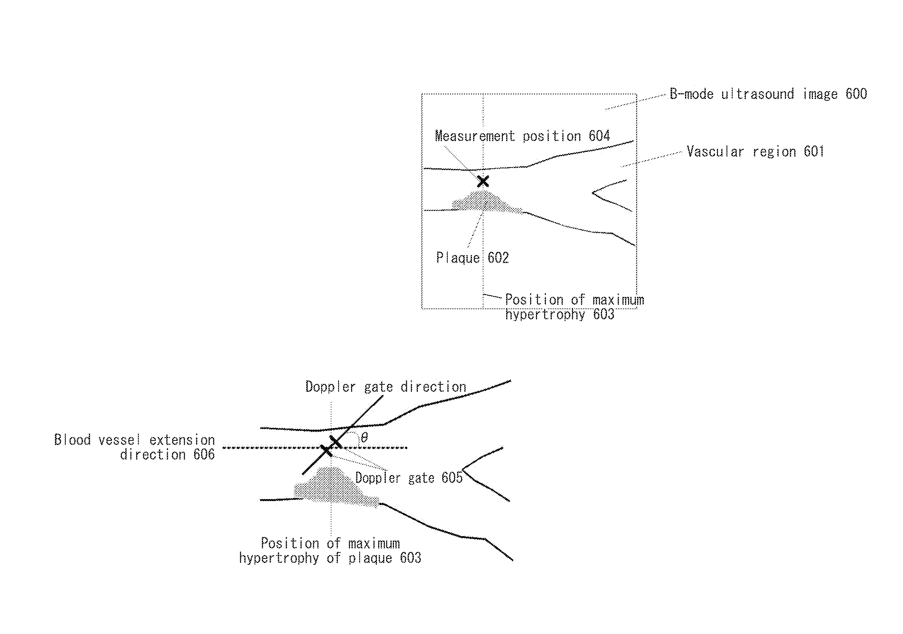
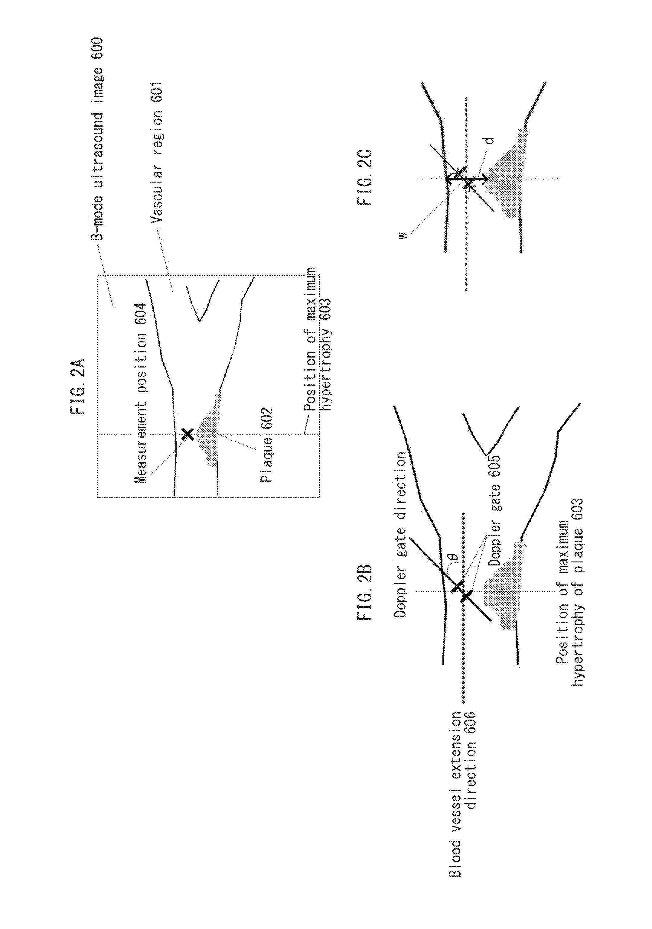
[0045]An ultrasound diagnostic apparatus, and a control method thereof, relating to a first embodiment are explained with reference to the drawings. An ultrasound diagnostic apparatus 10 relating to the first embodiment automatically determines position of a plaque or other part of a blood vessel based on shape of the blood vessel extracted from an ultrasound image, and performs measurement by Doppler ultrasound at the position which is determined. Herein, the term ultrasound image refers to a video image or a still image such as a B-mode ultrasound image, which is generated from a reception signal acquired by scanning a measurement target using an ultrasound probe. The term ultrasound image may also refer to a reception signal, or a signal resulting from processing of the reception signal, which is inclusive of sufficient information for generating a video image or a still image.

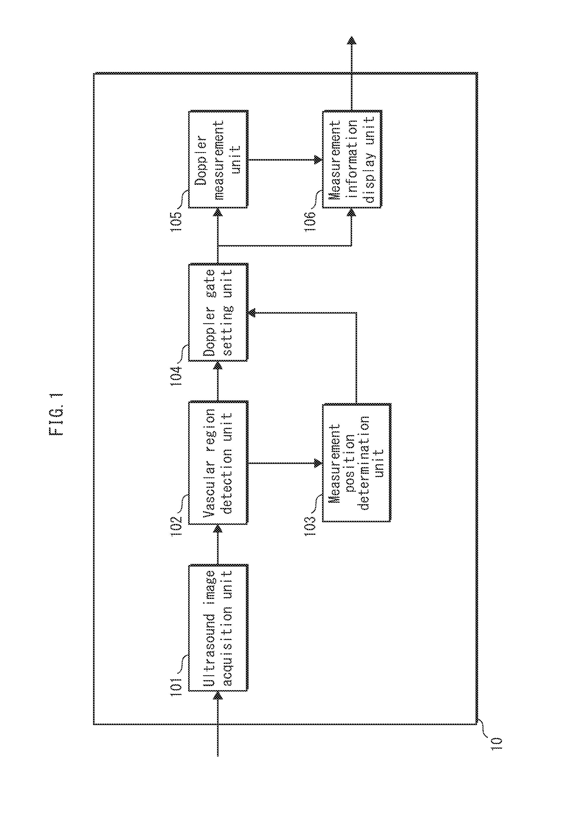
[0046]FIG. 1 is a block diagram illustrating configuration of the ultrasound diagnostic apparatus ...

modified example

[0083]In the first embodiment, a plaque is detected from the vascular region as the specific part and one or more measurement positions are determined in proximity to the plaque. In the present modified example, explanation is given of a configuration in which blood flow velocity is measured by determining one or more measurement positions based on typical shape of a part of a vascular wall which is susceptible to formation of a plaque.

[0084]FIG. 6 is a longitudinal cross-sectional image of the carotid artery that illustrates an example of determining measurement positions. The measurement position determination unit 103 detects, as specific parts, a boundary 611 between the common carotid artery and the carotid sinus, and a boundary 612 between the carotid sinus and the internal and external carotid arteries, based on shape of the media-adventitia interface. The boundary 611 between the common carotid artery and the carotid sinus is detected based on change, in terms of the longitu...


PUM


Abstract

An ultrasound diagnostic apparatus measures blood flow velocity by emitting ultrasound towards a measurement target and receiving a reflected wave, via an ultrasound probe. The ultrasound diagnostic apparatus includes an ultrasound image acquisition unit, a vascular region detection unit, a measurement position determination unit, and a Doppler gate setting unit. The ultrasound image acquisition unit acquires an ultrasound image which has been captured of the measurement target. The vascular region detection unit detects, from the ultrasound image, a vascular region corresponding to a blood vessel. The measurement position determination unit detects a specific part of the vascular region based on vascular region shape and determines, in accordance with the specific part, one or more measurement positions in the vascular region in terms of longitudinal direction thereof. The Doppler gate setting unit sets, with respect to each measurement position, a Doppler gate in a lumen region of the vascular region.

Description

[0001]This application is based on an application No. 2013-080941 filed in Japan on Apr. 9, 2013, the contents of which are hereby incorporated by reference.BACKGROUND OF THE INVENTION[0002](1) Field of the Invention[0003]The present invention relates to an ultrasound diagnostic apparatus, and a control method thereof, that automatically sets a measurement position for Doppler ultrasound based on results of ultrasound image analysis.[0004](2) Description of the Related Art[0005]Diagnostic imaging apparatuses which are commonly used on living organisms include X-ray diagnostic apparatuses, MRI (Magnetic Resonance Imaging) diagnostic apparatuses and ultrasound diagnostic apparatuses. Among the above apparatuses, ultrasound diagnostic apparatuses in particular have advantages in terms of non-invasiveness and real time usage, and are widely used in health examinations and diagnosis.[0006]An ultrasound diagnostic apparatus may use various different measurement methods. In brightness mode...

Claims


Application Information

Patent Timeline
Patent Type & Authority Applications(United States)
IPC IPC(8): A61B8/06A61B8/08
CPCA61B8/06A61B8/08A61B8/488A61B8/0891A61B8/4245A61B8/483A61B8/5223G16H50/30
Inventor TOMA, TADAMASAOHMIYA, JUNTOJI, BUMPEI
Owner KONICA MINOLTA INC
Why Eureka
Try Eureka