System and method for processing samples

Active Publication Date: 2014-10-16
BECKMAN COULTER INC
View PDF0 Cites 54 Cited by
  • Summary
  • Abstract
  • Description
  • Claims
  • Application Information

AI Technical Summary

Benefits of technology

[0023]Embodiments of the technology relate to systems

Problems solved by technology

Varying implementations of these laboratory processes present challenges for automation.
However, the conventional recappers are only able to utilize one type of cap for recapping and thus these recappers are unable to accommodate different tubes needing different types of caps.
However, the image analysis algorithms are typically limited to the identification of only the single object and are unable to identify other details of the objects within the image.
These urgent sample tube markers are inefficient and non-automated, requiring a laboratory technician to apply and/or handwrite the indication of urgency.
However, these devices are typically stand-alone devices that are manually operated by the laboratory system.
However, the current robotic arm technology is generally limited to gripping either the sample tubes or centrifuge adapter, but not both.
Additionally, the current technology cannot perform any additional functions besides the gripping features.
The temporary unavailability of subassemblies in the system due to failure, maintenance, scheduled service, etc. may cause a complete stop of the whole system, and currently there does not exist an efficient way to continue the operation of the system during such an unavailability.
However, the obstacle detection used in the conventional systems is discontinuous, such that obstacles are detected on a periodic basis.
This can lead to an obstacle being undetected during the interim.
However, if a puck failed to operate properly, the puck transport system may become jammed.
However, the puck is only able to determine which action

Method used


Image

  • System and method for processing samples
  • System and method for processing samples
  • System and method for processing samples

Examples


first embodiment

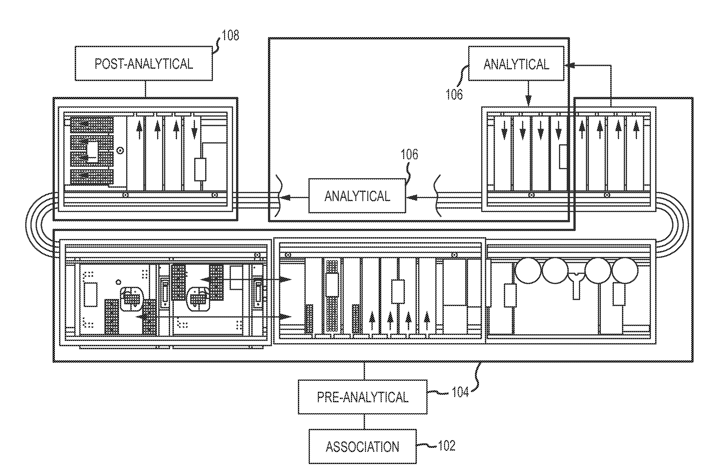
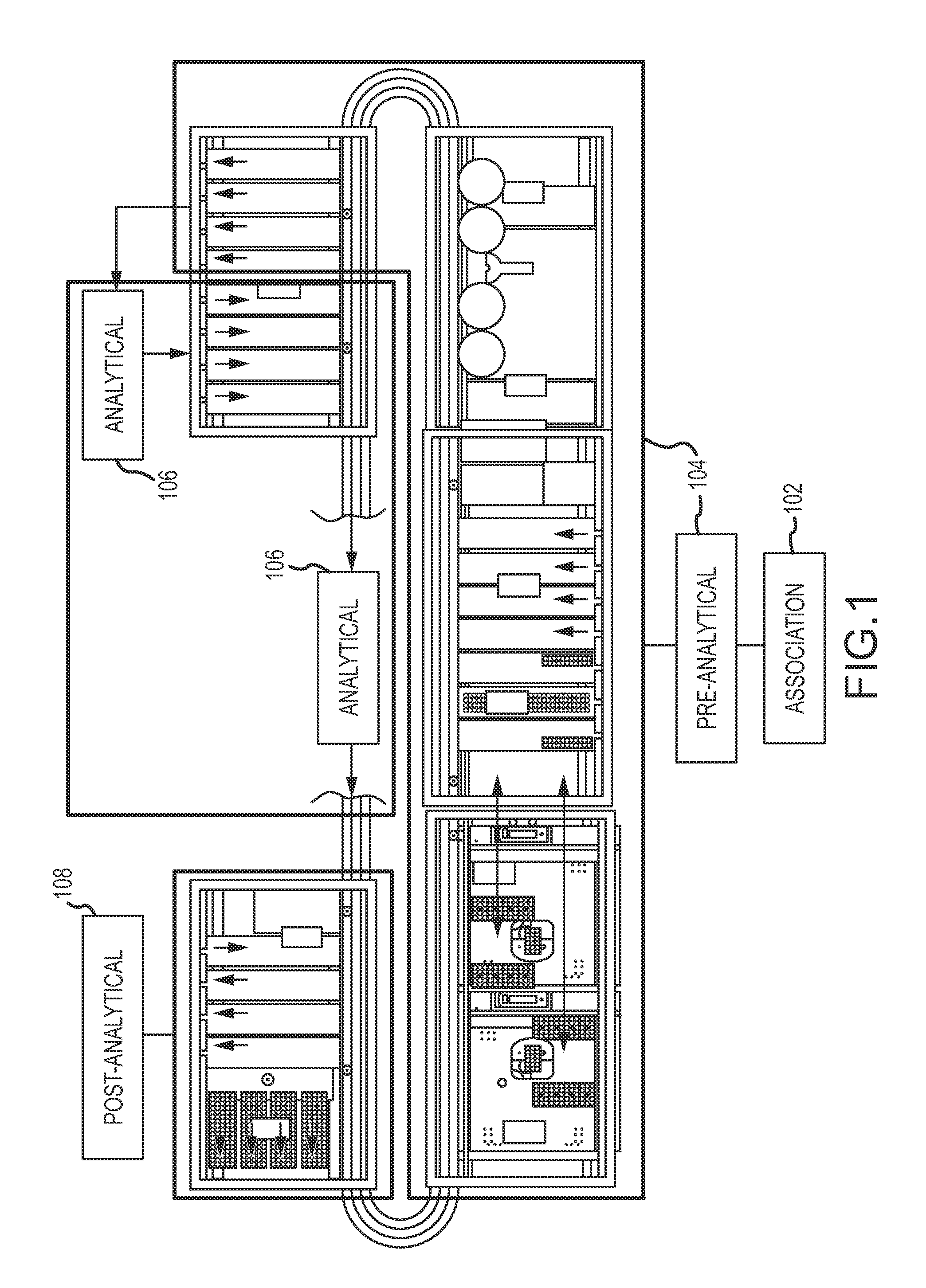
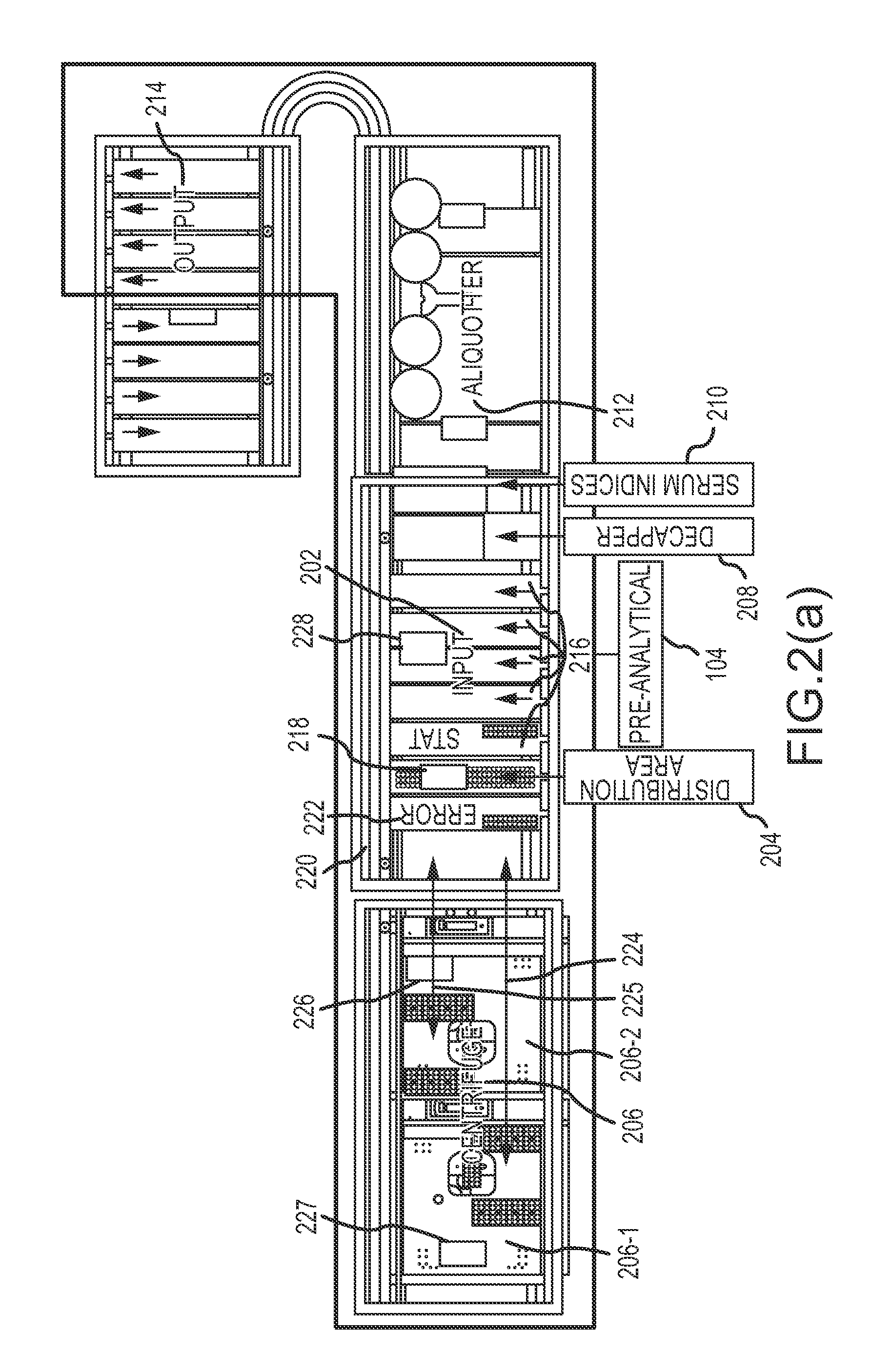
[0270]FIG. 16 depicts an illustrative adapter swap sequence for a centrifuge according to a Although a single centrifuge adapter 1002 is shown in centrifuge 206, positions B, E, H and K of centrifuge 206 correspond to four centrifuge buckets that can receive centrifuge adapters 1002. A centrifuge with four centrifuge buckets is shown in FIG. 16. A previously unloaded centrifuge adapter (e.g., centrifuge adapter 1002) is moved by centrifuge adapter gripper 227 from shuttle position A to temporary holding area M (1602), as shown at 1604. An unloaded centrifuge adapter is a centrifuge adapter from which all sample tubes have been removed. Next, a previously centrifuged (“spun”) centrifuge adapter is moved by centrifuge adapter gripper 227 from area B of centrifuge 206 to the vacant space on shuttle position A, as indicated at operation 1606. Shuttle positions A, J, G, and D can be collectively referred to as first shuttle position 1610. At operation 1606, the centrifuge adapter 1002 i...

second embodiment

[0544]FIGS. 77(a)-(b) show tubular holder 7704, according to a Tubular holder 7704 may have a keyhole opening 7712 configured to match the cross-sectional profile of bolt 7700 with pins 7706. When bolt 7700 is inserted into tubular holder 7704, gripper pins 7606 fit through keyhole opening 7712 and are lowered below a shelf 7708. When the pins 7706 are below shelf 7708, gripper 227 may rotate bolt 7700 (e.g., by 90 degrees) such that the pins 7706 are seated in notch 7712. In this manner, the gripper can lift and transport centrifuge adapter 1002. To release bolt 7700 from centrifuge adapter tubular holder 7704, the bolt is rotated in the opposite direction.

[0545]Various measures may be implemented to prevent the centrifuge adapter from swinging during x- and y-axis movement of centrifuge adapter gripper 227. For example, gripper 227 may be operated at the extent of its z-axis range such that the top of the adapter is pressed against the underside of the housing of gripper 227. In ...


PUM

PropertyMeasurementUnit
Weightaaaaaaaaaa
Timeaaaaaaaaaa
Diameteraaaaaaaaaa

Abstract

An analytical laboratory system and method for processing samples is disclosed. The system includes a manager unit, as well as an aliquotter unit and a centrifuge unit.

Description

CROSS-REFERENCES TO RELATED APPLICATIONS[0001]This application claims priority to U.S. Provisional Patent Application No. 61 / 556,667, filed Nov. 7, 2011 and entitled “Analytical System and Method for Processing Samples.” This application also claims priority to U.S. Provisional Patent Application No. 61 / 616,994, filed Mar. 28, 2012 and entitled “Analytical System and Method for Processing Samples.” This application further claims priority to U.S. Provisional Patent Application No. 61 / 680,066, filed Aug. 6, 2012 and entitled “Analytical System and Method for Processing Samples.” All of these applications are herein incorporated by reference in their entirety for all purposes.BACKGROUND[0002]Conventional medical laboratory systems implement a variety of processes for analyzing medical specimens. These systems have become more efficient due to the increasing extent to which laboratory analysis processes have become automated. However, there remain several components of medical laborato...

Claims


Application Information

Patent Timeline
IPC IPC(8): G01N35/10G01N35/00
CPCB01D21/262G01N35/10B04B15/00B25J11/00B04B9/146G01N35/00732G01N35/0099G01N35/04B04B2011/046G01N2035/00495G01N2035/0405G01N2035/0462G01N2035/0491G01N2035/1025G01N2035/1032G01B11/02G01B11/08G01B11/10G01M1/14G01N21/27G01N35/1009B01L3/5021B04B7/02B04B7/08G01F23/292G01N2035/0489Y10T29/49826B04B9/14B04B11/04B04B13/00B04B2009/143B04B2013/006B65D51/24B65G47/28G01B11/24G01F23/00G01L19/08G01N35/00584
Inventor JOHNS, CHARLES W.
Owner BECKMAN COULTER INC
Why Eureka
Try Eureka