Method and apparatus for generating steam for the recovery of hydrocarbon

a hydrocarbon and hydrocarbon technology, applied in steam superheaters, steam boiler components, fluid removal, etc., can solve the problems of reducing the strength of materials and their service life, heat transfer, and difficulty in native state pumping, so as to reduce the amount of fresh water, reduce the environmental impact of steam generation, and reduce the amount of blowing water

Active Publication Date: 2014-10-16
DEN NORSKE STATS OLJESELSKAP AS
View PDF2 Cites 9 Cited by
  • Summary
  • Abstract
  • Description
  • Claims
  • Application Information

AI Technical Summary

Benefits of technology

[0125]Reduced amount of blow down water and concomitant reduced amount of fresh water required. Together these factors significantly decrease the environmental impact of steam generation.
[0126]The methods and apparatus of the present invention may also be advantageously used in a method of cleaning an apparatus for generating steam and in particular for removing hydrocarbon from the apparatus. In this method supercritical steam is preferably generated by a method as hereinbefore defined. Instead of transporting the supercritical steam to an expansion unit, however, oxygen is added to the supercritical steam and the resulting O2 containing supercritical steam is used for cleaning. The O2 present in the supercritical steam will combust any organics it en

Problems solved by technology

This is partly because heavy hydrocarbons are generally difficult to recover by conventional recovery processes and thus have not been exploited to the same extent as non-heavy hydrocarbons.
Heavy hydrocarbons possess very high viscosities and low API (American Petroleum Institute) gravities which makes them difficult, if not impossible, to pump in their native state.
The deposits form a thermal barrier on the heat surfaces and increase the temperature of the surfaces which ultimately reduces the strength of their material and their service lifetime.
The deposits also reduce the heat transfer to water to generate steam thus reducing the quantity and quality of the steam subsequently produced by the steam generator.
On the other hand, however, this means that 20% by weight of the water that is fed into the boiler is not converted to steam which represents a significant inefficiency.
Evaporation can also be used although this is energy intensive.
The effective treatment of large volumes of separated water from hydrocarbon recovery operations economically is therefore a challenge.
Even with care, it has an environmental impact.
A major pr

Method used


Image

  • Method and apparatus for generating steam for the recovery of hydrocarbon
  • Method and apparatus for generating steam for the recovery of hydrocarbon
  • Method and apparatus for generating steam for the recovery of hydrocarbon

Examples


Embodiment Construction

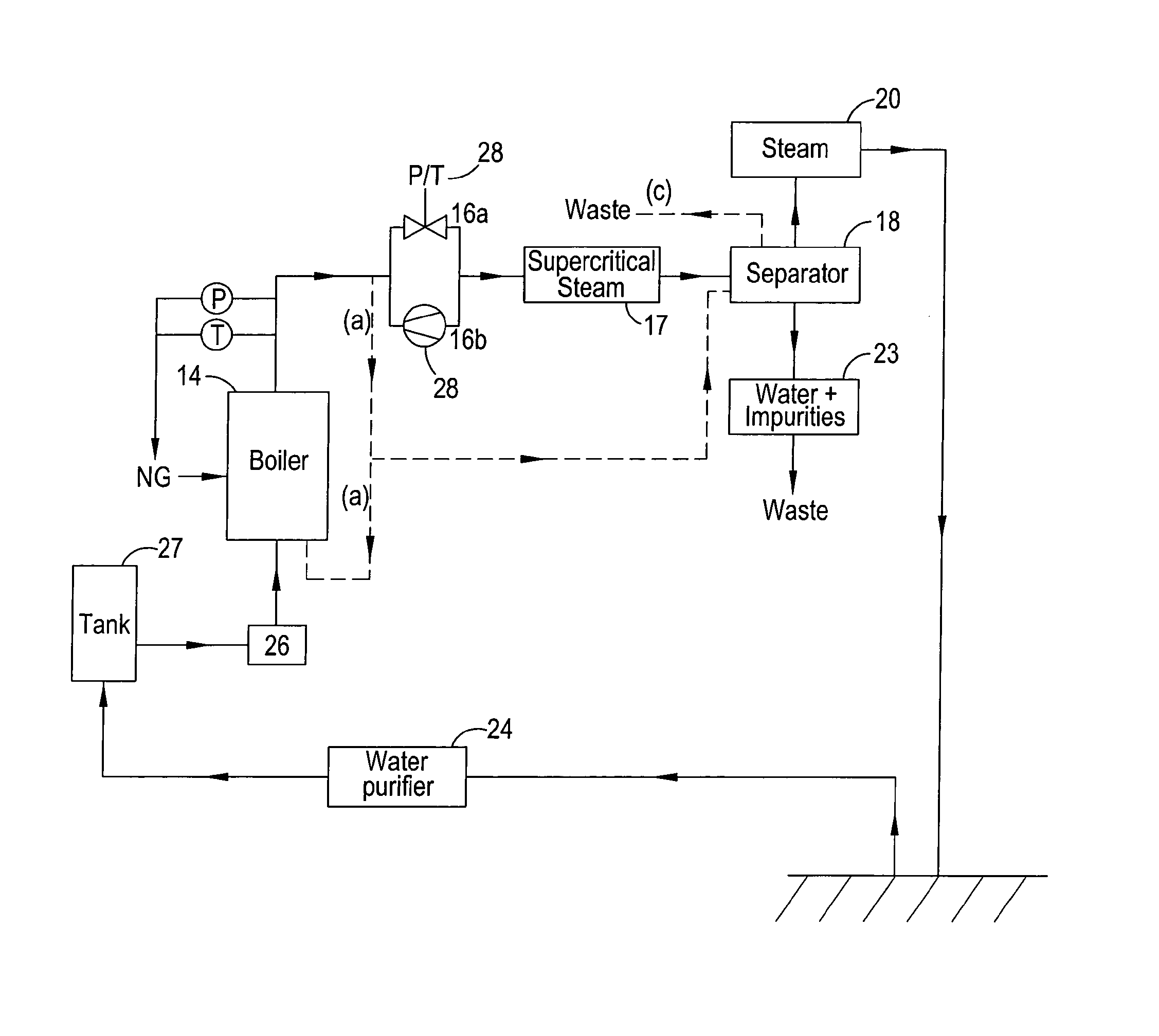
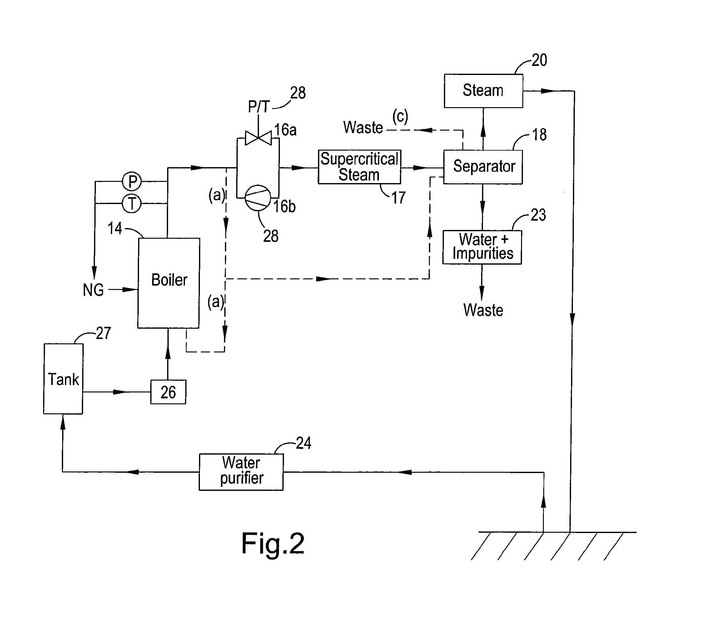
[0150]In FIGS. 1b, 2 and 3 features that are common are designated by the same reference numeral.

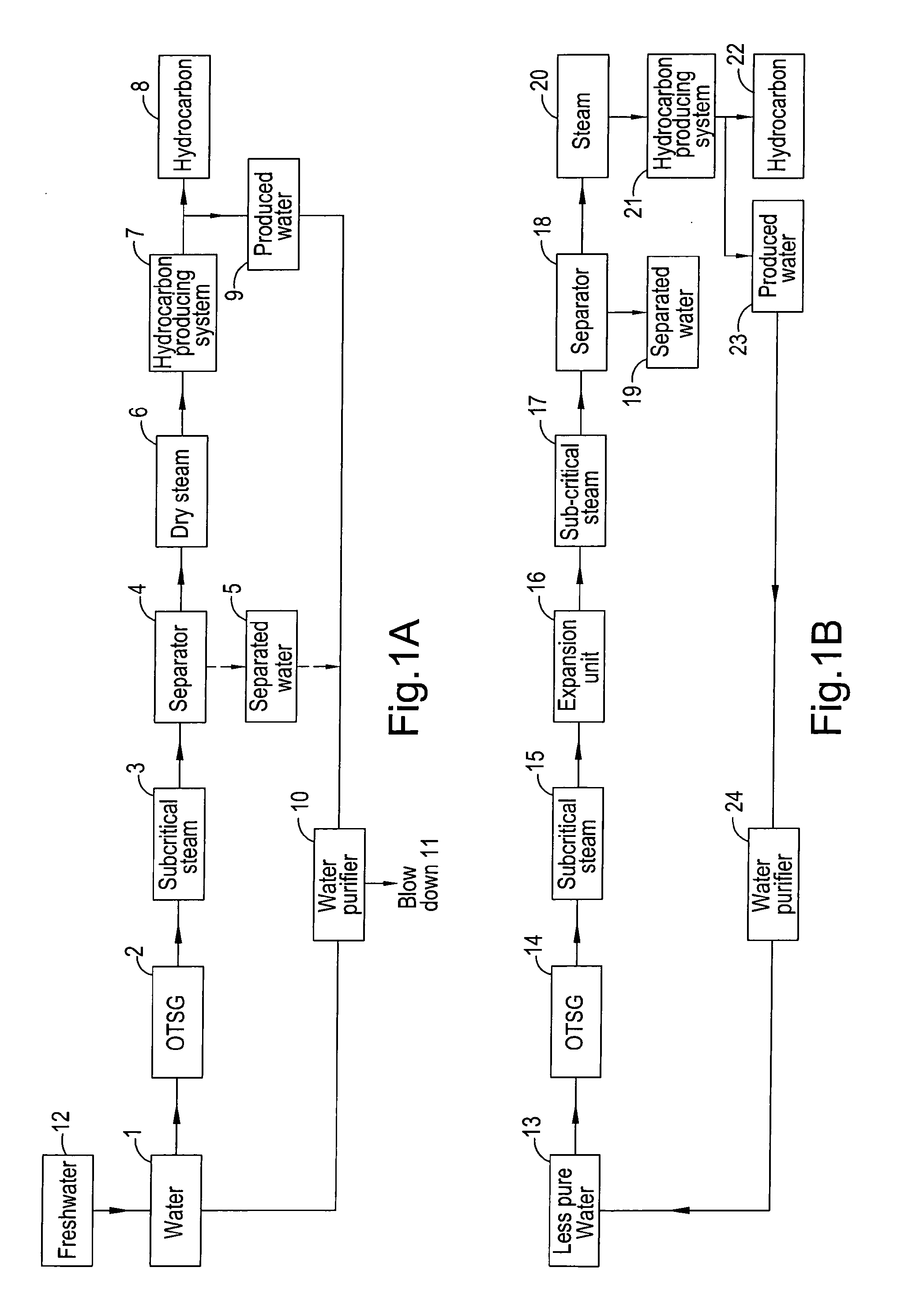
[0151]Referring to FIG. 1a, it shows a schematic diagram of the generation of steam by a conventional technique. Thus water 1, which is generally purified to a significant level, is pumped to a OTSG 2 wherein subcritical steam 3 is generated. Typically the OTSG 2 is operated under conditions that produce a steam quality of about 80%. Under such conditions the steam generator is less likely to run dry which leads to the production of significant amounts of precipitate that sticks to the heat transfer surfaces of the OTSG. The subcritical steam 3 is usually fed to a steam separator 4 to remove the water 5. The resulting dry steam 6 is fed to the hydrocarbon producing system 7 wherein it mobilises hydrocarbon to enable its recovery. When the mobilised hydrocarbon 8 is produced at the surface, significant amounts of water 9 is also produced. This water 9 comprises impurities, e.g. hydrocarbo...


PUM


Abstract

The present invention provides a method of generating steam for the recovery of hydrocarbon from a hydro-carbon producing system comprising: (i) generating supercritical steam from water; (ii) converting said supercritical steam to a subcritical steam; and (iii) injecting said subcritical steam into said system.

Description

[0001]The present invention relates to a method of generating steam for the recovery of hydrocarbon and to a method of producing hydrocarbon from a hydrocarbon producing system using the afore-mentioned method of steam generation. The invention further relates to an apparatus for generating steam for the recovery of hydrocarbon and to a system for producing hydrocarbon from a hydrocarbon producing formation.BACKGROUND[0002]Heavy hydrocarbons, e.g. bitumen, represent a huge natural source of the world's total potential reserves of oil. Present estimates place the quantity of heavy hydrocarbon reserves at several trillion barrels, more than 5 times the known amount of the conventional, i.e. non-heavy, hydrocarbon reserves. This is partly because heavy hydrocarbons are generally difficult to recover by conventional recovery processes and thus have not been exploited to the same extent as non-heavy hydrocarbons. Heavy hydrocarbons possess very high viscosities and low API (American Petr...

Claims


Application Information

Patent Timeline
IPC IPC(8): E21B43/24F22B37/26F22G7/00F22B29/06
CPCE21B43/2406F22B29/067E21B43/24F22G7/00F22B37/26F01K7/32F22B37/48
Inventor JOHNSEN, STEN EGILGRONSTAD, LEIF KARESORLIE, CARSTEN FRITHJOF
Owner DEN NORSKE STATS OLJESELSKAP AS
Why Eureka
Try Eureka