
Launch vehicle and system and method for economically efficient launch thereof

a technology for rocket launch and payload, which is applied in the field of systems, methods and apparatuses for the launch of payloads, can solve the problems of relying solely on rocket launch, no alternative technology to date has been proven useful and reliable, and the need for large explosion force, etc., to achieve the effect of long orbital lifetime, longer orbital lifetime and longer orbital lifetim

Active Publication Date: 2014-10-16
8 RIVERS CAPTTAL LLC
View PDF24 Cites 12 Cited by
  • Summary
  • Abstract
  • Description
  • Claims
  • Application Information

AI Technical Summary

Benefits of technology

The patent text describes a new device that can generate very high velocities and pressures using a launch from the Earth. These velocities can be reduced using special cooling techniques, and the device is designed to have low discharge rates and low eddy current losses.

Problems solved by technology

As the mass of the object being accelerated increases, however, the explosive force required greatly increases.
Although much work has been done in attempting to develop alternative technologies for rapid acceleration of large payloads, such as electromagnetic launchers and plasma arc acceleration, no alternative technology to date has been proven useful and reliable, particularly in the launch of space vehicles.
In relation to space launch, while rocket propulsion is a long proven technology, reliance solely on rocket launch is problematic in that it remains expensive, dangerous, and is dominated by government funding.
Such problems are illustrated by the retirement and lack of suitable replacement for the National Aeronautic and Space Administration's Space Shuttle program.
This has hampered advancements in certain technologies, such as communications.
For example, satellite technologies have been slow and expensive to develop and are often outdated quickly after launch and satellite placement.
These factors and attendant continued government involvement have locked in high costs and low profits.
In particular, it is widely understood that present rocket launch technology can cost greater than $20,000 per kilogram of material for placement in an earth orbit.
These impose enormous challenges in designing payloads that can survive the launch and still accomplish complex tasks after launch.
Moreover, the persistently high costs of space launch mean government spending will continue to be an important factor in space launch technologies, and profitability will continue to remain low.

Method used


Image

  • Launch vehicle and system and method for economically efficient launch thereof
  • Launch vehicle and system and method for economically efficient launch thereof
  • Launch vehicle and system and method for economically efficient launch thereof

Examples


example

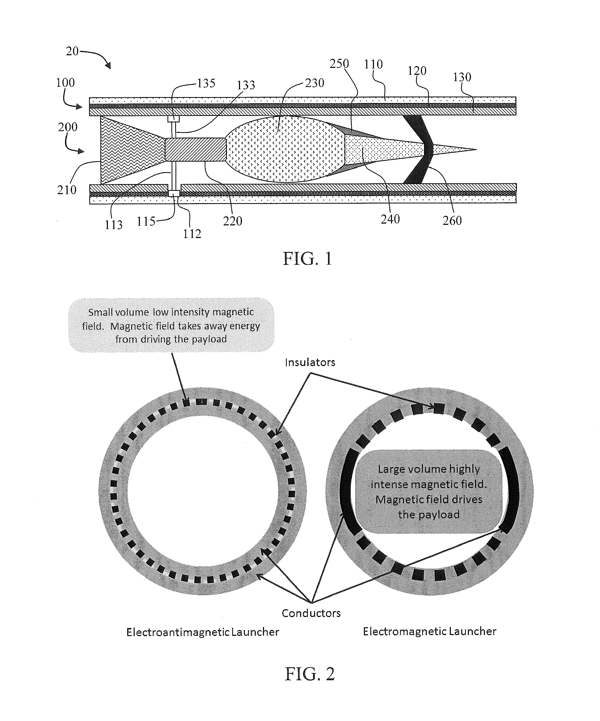
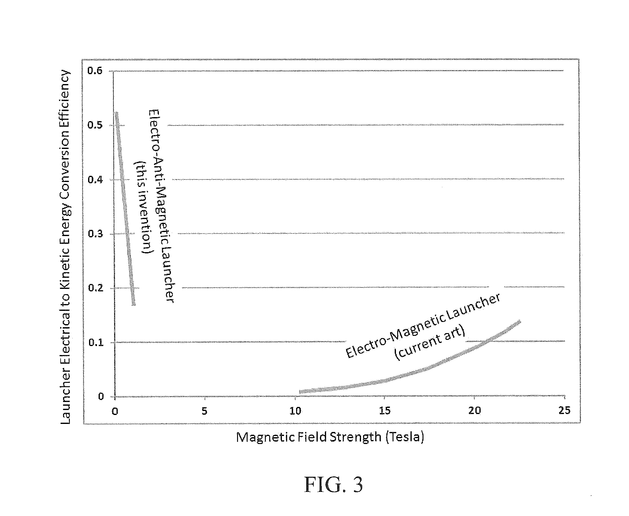
[0241]Mathematical modeling of launch systems was carried out to exemplify the advantages of the presently disclosed EAM launcher, particularly in relation to typical, prior art EM launchers.

F=MA=0.5×L′×I2

F=Force in Newtons

M=Mass in kg

[0242]A=acceleration in meters per second squared

L′=the increase in inductance per meter of travel in the launch tube in microhenries per meter

I=current in amps

Modeling of a Typical Known Art Railgun (for a 1 Ton Payload)

L′=5 E-7 H / m


PUM


Abstract

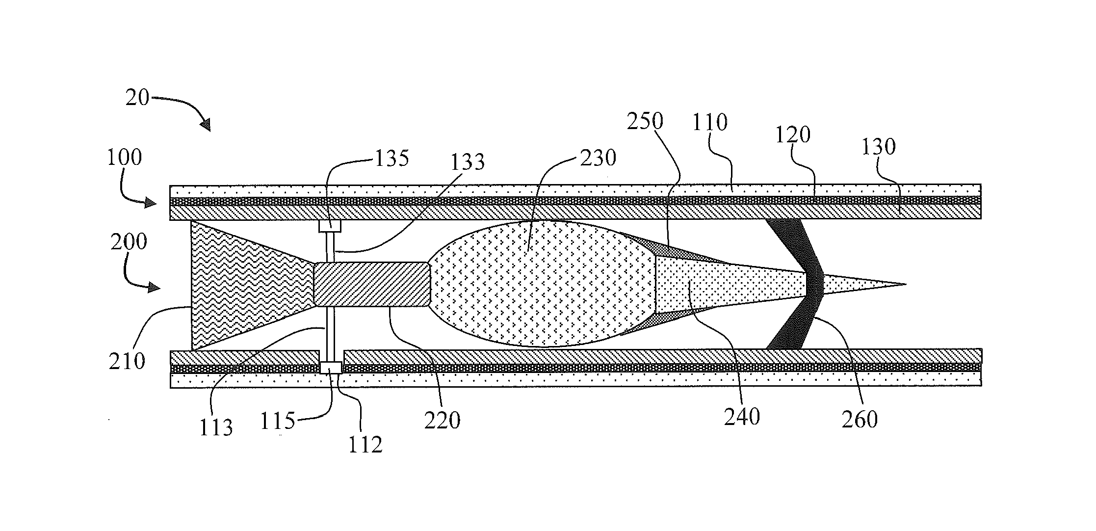
The present disclosure relates to a launch system, a launch vehicle for use with the launch system, and methods of launching a payload utilizing the launch vehicle and / or the launch system. The disclosure can provide for delivery of the payload at a terrestrial location, an Earth orbital location, or an extraorbital location. The launch vehicle can comprise a payload, a propellant tank, an electrical heater wherein propellant, such as a light gas (e.g., hydrogen) is electrically heated to significantly high temperatures, an exhaust nozzle from which the heated propellant expands to provide an exhaust velocity of, for example, 7-16 km / sec, and sliding electrical contacts in electrical connection with the electrical heater. The launch vehicle can be utilized with the launch system, which can further comprise a launch tube formed of concentric electrically conductive tubes, as well as an electrical energy source, such as a battery bank and associated inductor.

Description

CROSS-REFERENCE TO RELATED APPLICATIONS[0001]The present application claims priority to U.S. Provisional Patent Application No. 61 / 799,931, filed Mar. 15, 2013, the disclosure of which is incorporated herein by reference in its entirety.FIELD OF THE DISCLOSURE[0002]The present disclosure relates to systems, methods, and apparatuses for launch of a payload. More particularly, the payload may be intended for space launch or delivery to a terrestrial location, and the present disclosure can provide for acceleration of the payload from a launch tube to its desired location.BACKGROUND[0003]Many means are known for accelerating an object. Relatively small projectiles are efficiently accelerated via controlled explosive charges, such as with gunpowder. As the mass of the object being accelerated increases, however, the explosive force required greatly increases. For example, chemical combustion rockets are presently the only means that have been shown to be effective for launching payloads...

Claims


Application Information

Patent Timeline
Patent Type & Authority Applications(United States)
IPC IPC(8): B64G1/40
CPCB64G1/409B64G1/402B64G1/00B64G1/40F41B6/00B64G1/4021B64G1/417B64G1/002F42B6/006F41A1/04F42B15/10F42B15/12F41B6/006F02K9/95B64G1/415F41F1/00F42C11/00F41F3/04F41F3/0406F42C11/04
Inventor PALMER, MILES R.
Owner 8 RIVERS CAPTTAL LLC
Learn More