Motor control device provided with power failure management

a technology of power failure management and control device, which is applied in the direction of motor/generator/converter stopper, dynamo-electric converter control, instruments, etc., can solve the problems of complex control of power failure management in ac power supply failure at the time of driving a motor, affecting the control of the motor, and power failure may not be detected by a power failure detection unit with respect, so as to simplify the control of power failure management and facilitate the extension of power failure managemen

Active Publication Date: 2014-10-16
FANUC LTD
View PDF1 Cites 18 Cited by
  • Summary
  • Abstract
  • Description
  • Claims
  • Application Information

AI Technical Summary

Benefits of technology

[0014]An object of the invention is to provide a motor control device that enables simplification of the control for power failure management in AC power supply failure at the time of driving a motor, and enables easily extending of the power failure management.

Problems solved by technology

Therefore, control for power failure management in AC power supply failure at the time of driving a motor may be complicated in order to avoid adverse effects due to different power failure detection timings by power failure detection units on motor control.
Adverse effects due to a difference between the power failure detection timing by a power failure detection unit with respect to a control unit and the power failure detection timing by a power failure detection unit with respect to an electric power supply unit may affect the motor control.
For instance, although power failure is detected by a power failure detection unit with respect to a control unit, power failure may not be detected by a power failure detection unit with respect to an electric power supply unit.
In this case, it is impossible to stop a motor or retract a driven body driven by the motor in AC power supply failure at the time of driving the motor.
As described above, control for power failure management in AC power supply failure at the time of driving a motor may be complicated in order to avoid adverse effects due to a difference between the power failure detection timing by a power failure detection unit with respect to a control unit and the power failure detection timing by a power failure detection unit with respect to an electric power supply unit on motor control.
The aforementioned control may be further complicated, as the number of devices equipped with a power failure detection unit increases.
This makes it difficult to extend a device such as a power failure management device.

Method used


Image

  • Motor control device provided with power failure management
  • Motor control device provided with power failure management
  • Motor control device provided with power failure management

Examples


first embodiment

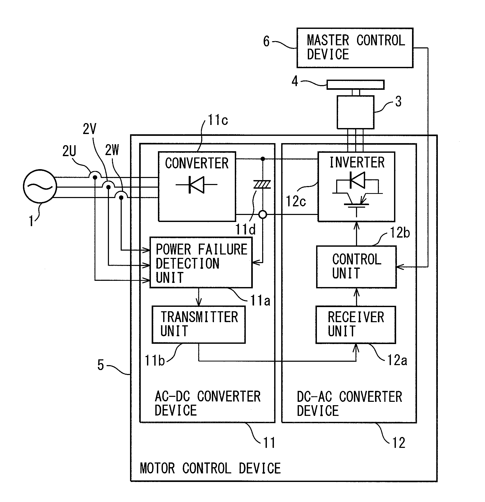
[0034]FIG. 1 is a diagram illustrating a system provided with a motor control device according to a The system illustrated in FIG. 1 is used in a machine tool. The system illustrated in FIG. 1 is provided with a 3-phase AC power supply 1 as an AC power supply, voltage detectors 2U, 2V, 2W, a motor 3, a driven body 4, a motor control device 5, and a master control device 6.

[0035]The voltage detectors 2U, 2V, 2W are provided on the output line of the 3-phase AC power supply 1 for detecting voltages of three phases i.e. U-phase voltage, V-phase voltage, W-phase voltage. Examples of the motor 3 include a gravity axis servo motor configured to drive the main shaft of a machine tool in the gravity axis direction (in Z-axis direction) by a screw feeding mechanism such as a ball screw / nut mechanism, a main shaft motor configured to drive a tool mounted on the main shaft of a machine tool, and a horizontal axis servo motor configured to drive a table of a machine tool on which a workpiece i...

second embodiment

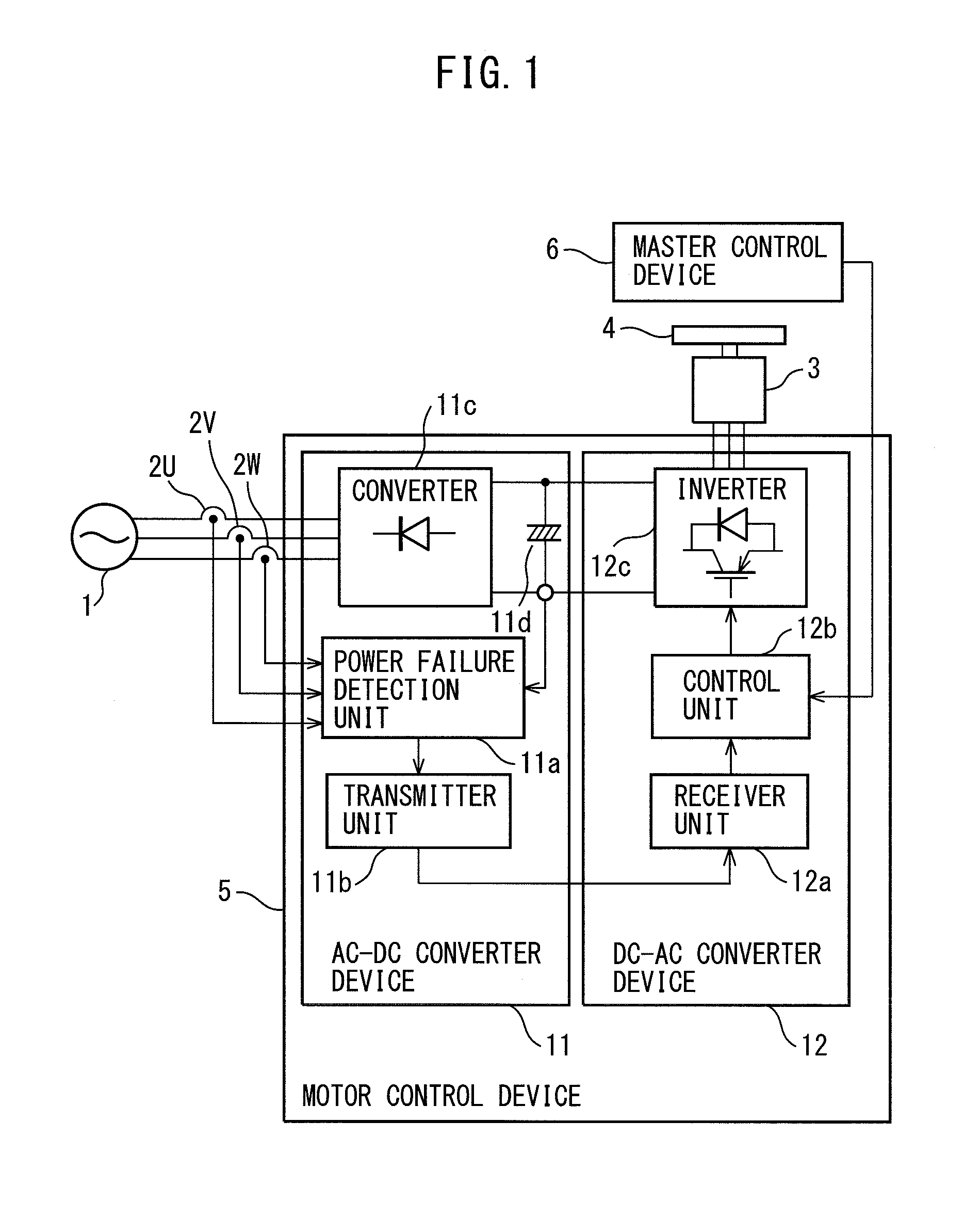
[0048]FIG. 2 is a diagram illustrating a system provided with a motor control device according to a The system illustrated in FIG. 2 is provided with a 3-phase AC power supply 1, voltage detectors 2U, 2V, 2W, a motor 3, a driven body 4, a motor control device 15, and a master control device 6.

[0049]The motor control device 15 is provided with an AC-DC converter device 11 and a DC-AC converter device 12′, and an electric power management device 13 as a second device. The DC-AC converter device 12′ has a control unit 12b and an inverter 12c. The electric power management device 13 has a receiver unit 13a, a regenerative electric power consumption control unit 13b, an electric power supply control unit 13b′, and an electric power supply control unit 13b″. In the embodiment, the AC-DC converter device 11 and the DC-AC converter device 12° connected thereto constitute a device 14 as a first device.

[0050]In the embodiment, the motor control device 15 is configured to detect power failure...

third embodiment

[0079]FIG. 9 is a diagram illustrating a system provided with a motor control device according to a The system illustrated in FIG. 9 is provided with a 3-phase AC power supply 1, voltage detectors 2U, 2V, 2W, a motor 3, a driven body 4, a motor control device 25, and a master control device 6.

[0080]The motor control device 25 is provided with an AC-DC converter device 11 as a first device, a DC-AC converter device 12, and an electric power management device 13′. The electric power management device 13′ has a regenerative electric power consumption control unit 13b, an electric power supply control unit 13b′, and an electric power supply control unit 13b″. In the embodiment, the DC-AC converter device 12 and the electric power management device 13′ connected thereto constitute a device 14′ as a second device.

[0081]In the embodiment, the motor control device 25 is configured to detect power failure of the 3-phase AC power supply 1 at the time of driving the motor 3, and to control th...


PUM


Abstract

A power failure detection unit in an AC-DC converter device detects power failure of a 3-phase AC power supply at the time of driving a motor, and generates a power failure detection signal in accordance with detection of power failure. A transmitter unit in the AC-DC converter device transmits the power failure detection signal using a cable, radio, or an optical fiber. A receiver unit in a DC-AC converter device receives the power failure detection signal transmitted from the transmitter unit.

Description

BACKGROUND OF THE INVENTION[0001]1. Field of the Invention[0002]The present invention relates to a motor control device provided with power failure management in AC power supply failure at the time of driving a motor.[0003]2. Description of the Related Art[0004]Conventionally, as disclosed in Japanese Laid-open Patent Publication No. 2011-101474, Japanese Laid-open Patent Publication No. 2011-209936, Japanese Patent No. 3,472,433, and Japanese Patent No. 3,616,759, for instance, there is proposed a motor control device provided with a power failure detection unit configured to detect AC power supply failure at the time of driving a motor and to generate a power failure detection signal in accordance with detection of power failure, and a control unit configured to control the motor for stopping the motor in response to detection of power failure, as a motor control device provided with power failure management in AC power supply failure at the time of driving a motor. In this config...

Claims


Application Information

Patent Timeline
Patent Type & Authority Applications(United States)
IPC IPC(8): H02P23/00H02P29/00H02P3/22
CPCH02P23/00H02P27/085H02P29/032
Inventor SAKAI, KOUJIROU
Owner FANUC LTD
Why Eureka
Try Eureka