Metal pipe corrosion monitoring device and use thereof

Active Publication Date: 2014-10-16
NAIGAI KAGAKU SEIHIN
View PDF3 Cites 14 Cited by
  • Summary
  • Abstract
  • Description
  • Claims
  • Application Information

AI Technical Summary

Benefits of technology

[0016]According to the present invention, it is possible to stably reproduce the actual environment in the metal pipe having the water phase region, the water line region and the vapor phase region, and thus it is possible to perform corrosion monitoring reflecting the actual environment in the metal pipe. That is, it is possible to measure the electric resistance of the one or more contact members that contact with the water phase region, the water line region and the vapor phase region in the steam introduction unit, and thus it is possible to assess which region in the metal pipe has the severest corrosion based on an electric resistance change.
[0017]As a result, it is possible to accurately assess, and accurately determine and evaluate the corrosion state in the actual environment (the water phase region, the water line region and the vapor phase region) in the current metal pipe, and at the same time, it is possible to take the most appropriate measures against the corrosion state at the right time. Specifically, it is possible to select the most appropriate agent (anticorrosion a

Problems solved by technology

Progression of corrosion causes metal-loss in the metal pip

Method used


Image

  • Metal pipe corrosion monitoring device and use thereof
  • Metal pipe corrosion monitoring device and use thereof
  • Metal pipe corrosion monitoring device and use thereof

Examples


embodiment 1

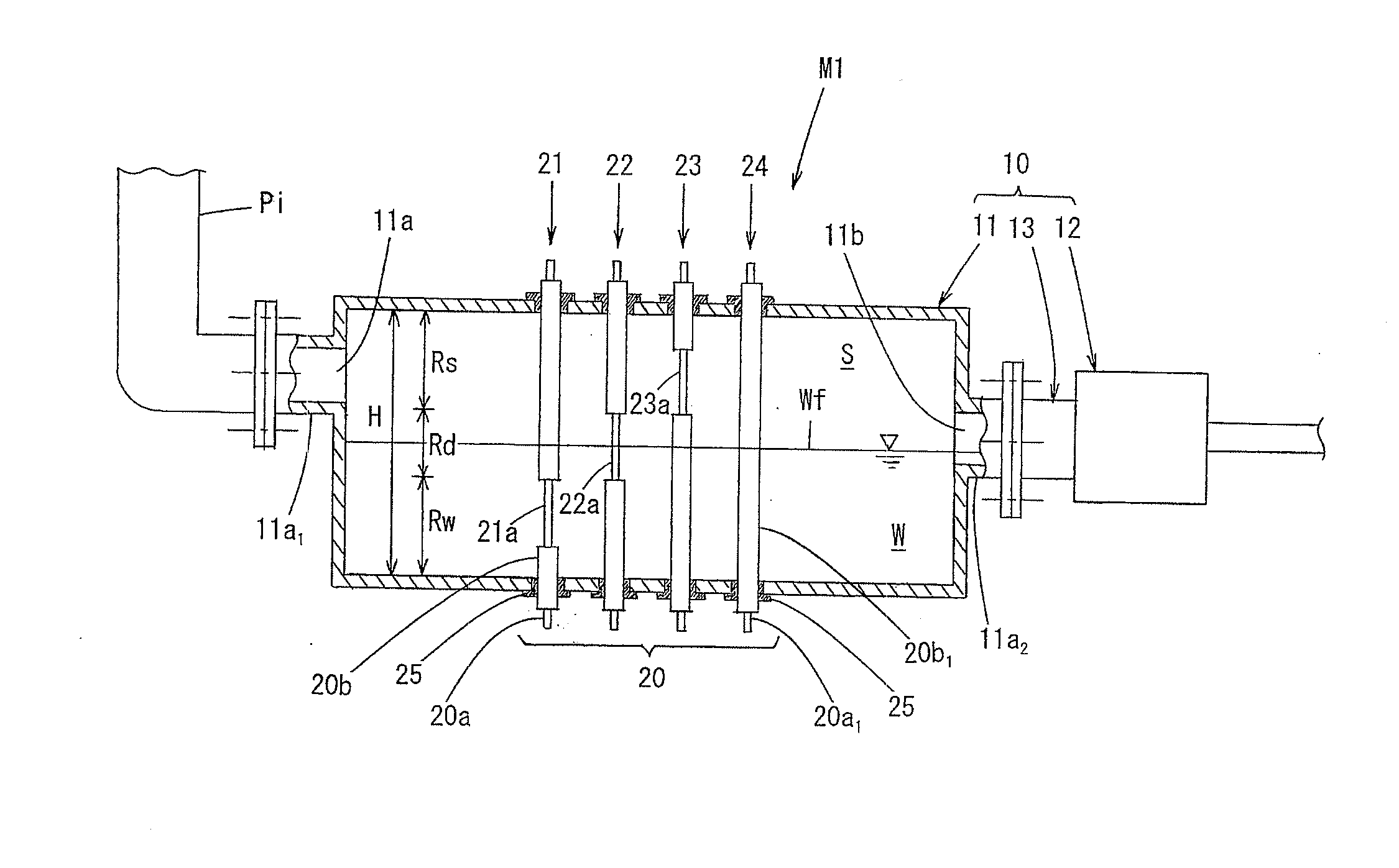
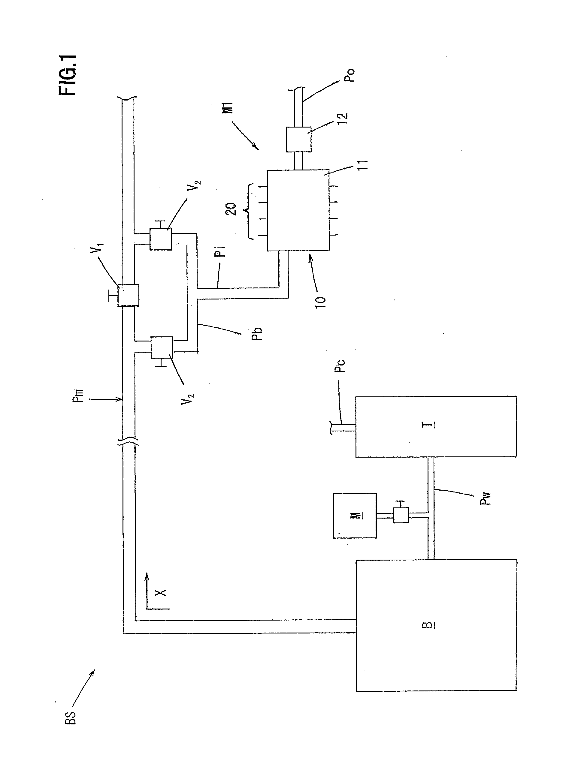
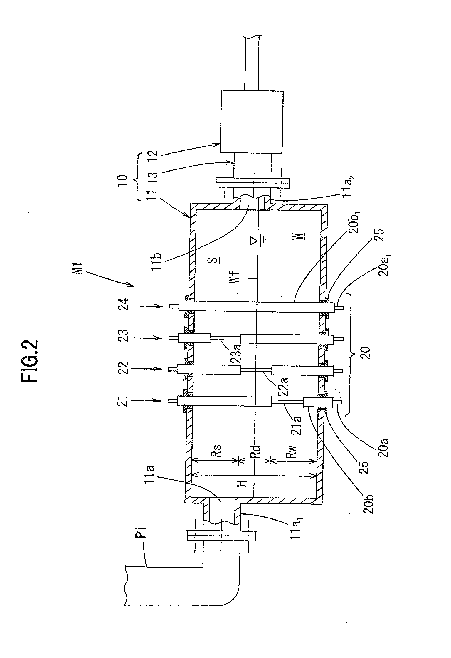
[0048]FIG. 1 is a diagram illustrating Embodiment 1 of the metal pipe corrosion monitoring device of the present invention in use. FIG. 2 is a schematic front sectional view showing an internal structure of the corrosion monitoring device of Embodiment 1. FIG. 3 is a circuit diagram showing an example of an electric circuit unit of the corrosion monitoring device of Embodiment 1.

[0049]As shown in FIG. 1, a metal pipe corrosion monitoring device M1 is a device that is provided to a boiler steam and condensate system BS to monitor corrosion of a metal pipe (steam piping) Pm.

[0050]In the case of Embodiment 1, the boiler steam and condensate system BS includes: a boiler B; a water supply tank T for supplying boiler water to a boiler B through a water supply pipe Pw; an agent feeding unit M connected to the water supply pipe Pw; and the metal pipe Pm for sending steam generated in the boiler B to a steam supply destination, not shown, wherein condensed water obtained through condensation...

embodiment 2

[0091]FIG. 4 is a schematic front sectional view showing an internal structure of a corrosion monitoring device of Embodiment 2. In FIG. 4, the same components as those in FIG. 2 are represented by the same reference numerals.

[0092]While the corrosion monitoring device M1 of Embodiment 1 has a configuration in which the first to third testing members 21 to 23 are removed from the container 11 and replaced with new ones, the corrosion monitoring device M2 of Embodiment 2 has a configuration in which the first to third testing members 21 to 23 are removed while remaining in the container 11.

[0093]Specifically, in the corrosion monitoring device M2 of Embodiment 2, a steam introduction unit 100 has a container 11 formed into a shape of a square cartridge (squared cylindrical shape), a steam trap 12 connected to the container 11, a holder 113 for detachably holding the container 11 and a connection pipe 13 for connecting the container 11 with the steam trap 12 via the holder 113. Thus, ...

embodiment 3

[0099]FIG. 5 (A) is a schematic front sectional view showing an internal structure of a corrosion monitoring device of Embodiment 3, and FIG. 5 (B) is a schematic left-side sectional view showing the internal structure of the corrosion monitoring device of Embodiment 3. In FIGS. 5 (A) and 5 (B), the same components as those in FIG. 2 are represented by the same reference numerals.

[0100]The corrosion monitoring device M3 of Embodiment 3 is different from the device of Embodiment 1 in a configuration of a container 211, a configuration of a corrosion testing unit 220 and a configuration of an electric circuit unit, not shown, and the other configurations in Embodiment 3 are the same as those in Embodiment 1. Hereinafter, differences of Embodiment 3 from Embodiment 1 will be mainly described.

[0101]The container 211 has a back portion 211B and a front portion 211A having an introduction port and a discharge port 211b, and is formed into a squared cylindrical shape by coupling flanges 21...


PUM


Abstract

A metal pipe corrosion monitoring device includes a steam introduction unit for introducing thereinto steam flowing through a metal pipe; and a corrosion testing unit provided in the steam introduction unit, characterized in that the steam introduction unit is configured to generate condensed water by condensing some of the steam to create a simulated environment similar to an actual environment in the metal pipe and discharge the condensed water above a predetermined water level to the outside. The corrosion testing unit has one or more contact members that contact with a water line region around a water surface of the condensed water in the steam introduction unit, a water phase region on a condensed water side and a vapor phase region on a steam side, and is configured to be able to measure an electric resistance of the one or more contact members.

Description

TECHNICAL FIELD[0001]The present invention relates to a metal pipe corrosion monitoring device and use thereof.BACKGROUND ART[0002]In a boiler generating steam, softened water or ion-exchange water is used as boiler water. According to circumstances, raw water (tap water, industrial water, underground water, river water, lake water, pond water, or the like) is used.[0003]In a boiler steam and condensate system including such a boiler and a metal pipe (for example, a ferrous metal pipe) for distributing steam from the boiler, the steam generated by the boiler cools to be condensed water inside the metal pipe. In the case of condensed water having a higher carbonic acid concentration, the pH thereof decreases to facilitate progression of corrosion of an inside surface of the metal pipe. Progression of corrosion causes metal-loss in the metal pipe, which may lead to a through hole, a crack, and the like.[0004]As Conventional Art 1 to monitor such corrosion of a metal pipe, there has be...

Claims


Application Information

Patent Timeline
IPC IPC(8): G01N17/04
CPCG01N17/04F22B37/38G01N17/006
Inventor MIYAZAKI, HARUHISAMURATA, KATSUMASAMARUGAME, KAZUOYOSHIDA, MASAKISUETAKE, YUSUKE
Owner NAIGAI KAGAKU SEIHIN
Why Eureka
Try Eureka