Syringe with Breakable Plunger for Arterial Blood Gas Sample Collection

Active Publication Date: 2014-10-16
BECTON DICKINSON & CO
View PDF1 Cites 4 Cited by
  • Summary
  • Abstract
  • Description
  • Claims
  • Application Information

AI Technical Summary

Benefits of technology

The invention is a device used for collecting fluid samples, such as blood samples, which is designed to prevent spillage of the sample during handling, storage, and transportation. The device includes a barrel with an internal reservoir and a plunger rod. The plunger rod is connected to the barrel at one end and has a stopper at the other end. When the device is ready for use, the plunger rod is disconnected from the barrel and the stopper is positioned to allow fluid or blood to flow into the reservoir. As the fluid flows, the stopper and the distal end of the plunger rod move towards the barrel's opening, where they contact a flange on the barrel's sidewall. Once enough fluid is collected, the needle assembly is removed from the patient and the tip cap is attached to prevent spillage. The technical effect of this invention is that it provides a secure and reliable device for collecting fluid samples while preventing spillage during handling, storage, and transportation.

Problems solved by technology

The need for the user to use two hands during the blood sample collection introduces unnecessary movement during the blood draw process and might cause discomfort to the patient.
However, the arterial blood collected using this type of syringe is exposed to air within the barrel interior of the syringe during the blood collection.
However, the plunger that is protruding from the syringe barrel makes handling and transportation of the syringe difficult and special care has to be taken not to dislodge the plunger thus preventing pneumatic tube transportation and increasing the time and resources required to transport and analyze the collected blood sample.
Such breakable connections possess sufficient structural integrity to resist breakage during normal use, but break upon application of additional force.
This additional force causes the breakable connection to shear, mechanically disconnecting the main body of the plunger rod from the distal portion, and hence disabling further use of the syringe.

Method used


Image

  • Syringe with Breakable Plunger for Arterial Blood Gas Sample Collection
  • Syringe with Breakable Plunger for Arterial Blood Gas Sample Collection
  • Syringe with Breakable Plunger for Arterial Blood Gas Sample Collection

Examples


Embodiment Construction

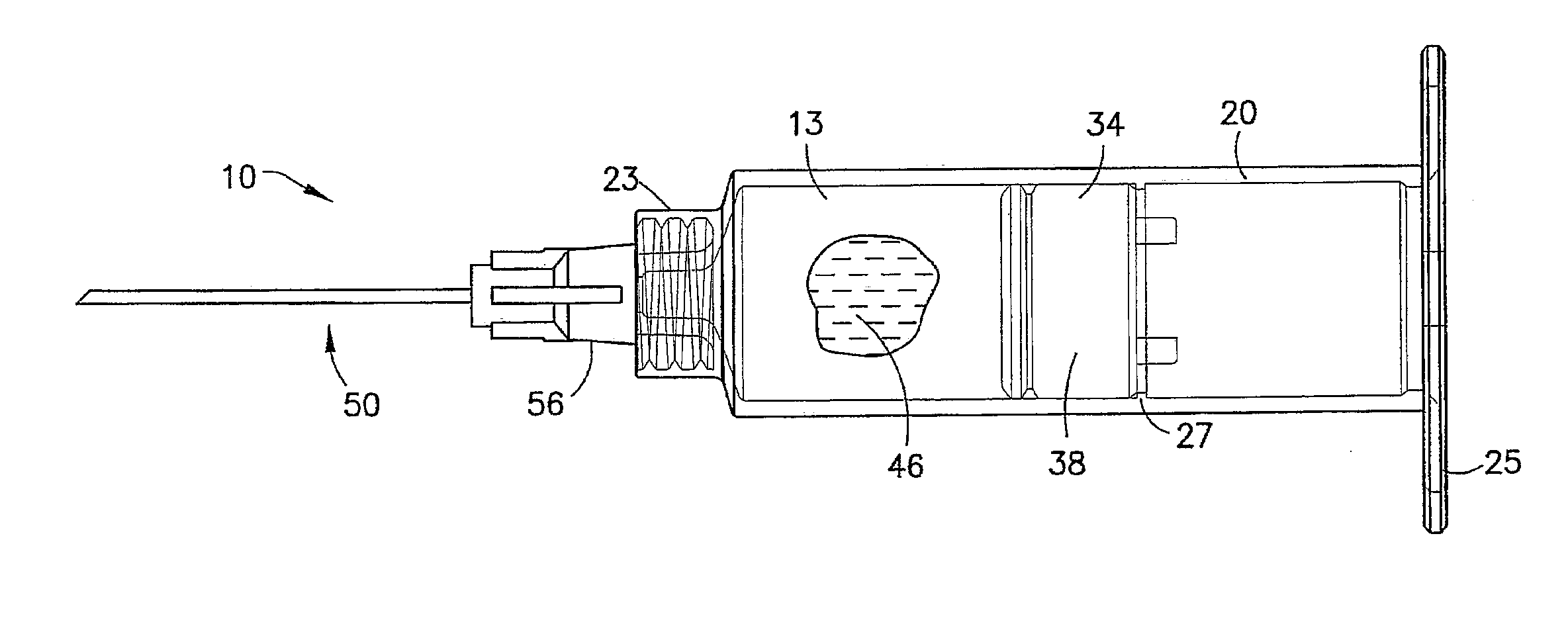
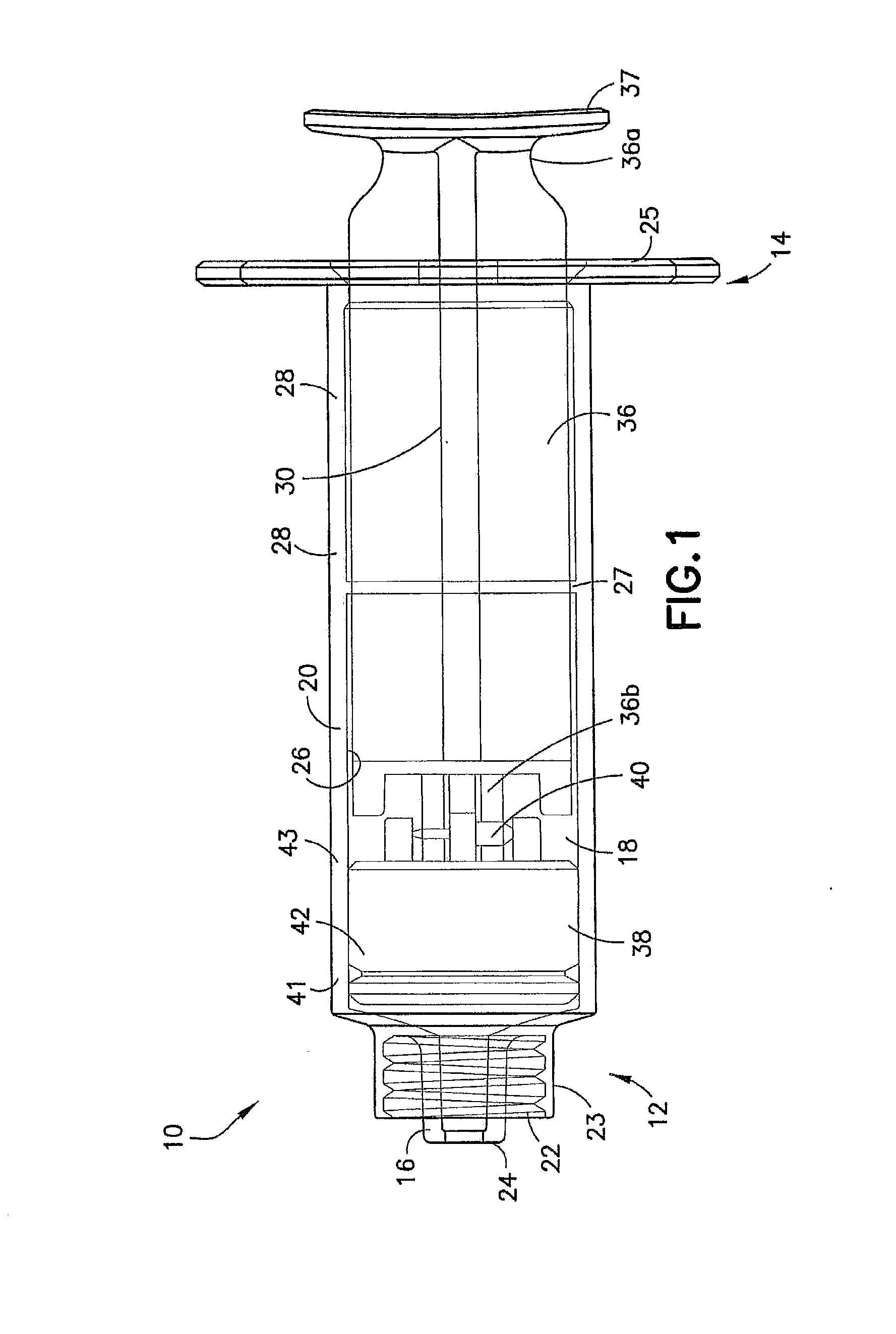
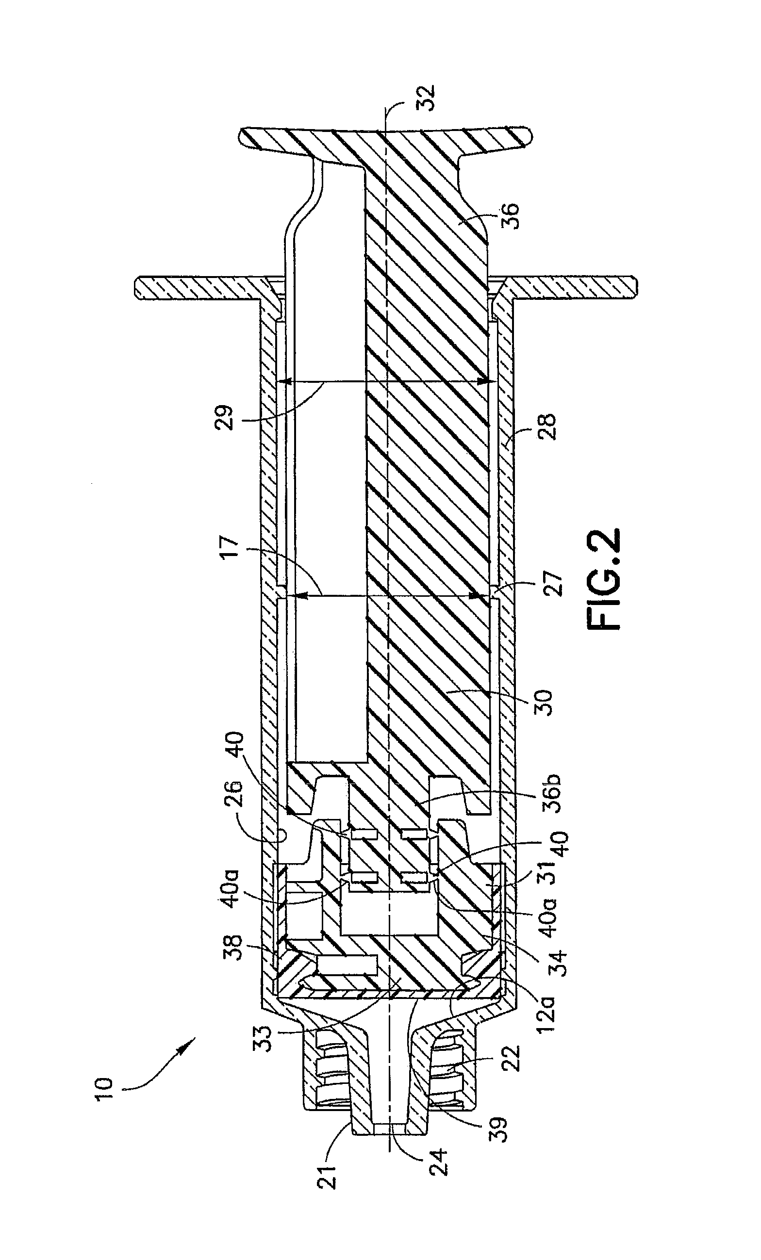
[0026]For purposes of the description hereinafter, the terms “upper”, “lower”, “right”, “left”, “vertical”, “horizontal”, “top”, “bottom”, “lateral”, “longitudinal”, and derivatives thereof shall relate to the invention as it is oriented in the drawing figures. However, it is to be understood that the invention may assume various alternative variations, except where expressly specified to the contrary. It is also to be understood that the specific devices illustrated in the attached drawings, and described in the following specification, are simply exemplary embodiments of the invention. Hence, specific dimensions and other physical characteristics related to the embodiments disclosed herein are not to be considered as limiting.

[0027]As used herein, the term “proximal” refers to a location on the blood collection assembly according to the embodiments of this invention that, during normal use, is closest to the clinician using the device and farthest from the patient in connection wi...


PUM


Abstract

A fluid collection assembly and method for use thereof is provided including a barrel with a plunger rod slidably inserted is disclosed. The assembly and method are particularly useful in the collection of arterial blood. The plunger rod includes a proximal portion, a distal portion with a stopper, and a breakable connector between the proximal and distal portions. In use, the assembly is primed with a liquid anticoagulant, the breakable connection is broken, and a fluid sample is collected with the arterial pressure causing the distal portion of the plunger rod to travel in a proximal direction along the barrel and contact an annular flange extending within the barrel. After collection, a tip cap can be applied to the assembly to prevent any spillage of the fluid sample during handling, storage, and transportation.

Description

BACKGROUND OF THE INVENTION[0001]1. Field of the Invention[0002]The present invention is directed to a fluid collection assembly and methods for use thereof and more particularly, to a fluid collection assembly including a breakable plunger rod for use in arterial blood collection. The present invention is also directed to a fluid collection assembly configured for containing an anti-coagulant for the immediate association with a fluid sample upon collection of the sample.[0003]2. Description of Related Art[0004]Arterial blood collection syringes are used for withdrawing and collecting arterial blood samples from the body of a patient. Once the blood sample is collected, it is subjected to diagnostic analysis for gases, electrolytes, metabolites, and other elements that are indicative of a condition of a patient. Various types of syringes have been devised for collecting arterial blood samples, which mainly comprise elements from a hypodermic syringe, i.e., a plastic or glass syring...

Claims


Application Information

Patent Timeline
IPC IPC(8): A61B5/15A61B5/153
CPCA61B5/15003A61B5/150236A61B5/150244A61B5/153A61B5/150389A61B5/150908A61B5/150259A61M5/31501A61M5/31511A61B5/150503A61B5/150732A61B5/150755
Inventor HOONG SIM, LEEKIANG HENG, LIM
Owner BECTON DICKINSON & CO
Why Eureka
Try Eureka