Apparatus for controlling a multi-winding rotary machine

a rotary machine and multi-winding technology, applied in the direction of motor/generator/converter stopper, dynamo-electric gear control, dynamo-electric converter control, etc., can solve the problem of increasing torque error, and achieve the effect of improving the responsiveness of the current control system and reducing the torque error of the rotary machin

Active Publication Date: 2014-10-23
DENSO CORP
View PDF5 Cites 22 Cited by
  • Summary
  • Abstract
  • Description
  • Claims
  • Application Information

AI Technical Summary

Benefits of technology

[0009]With this configuration, for each of the winding sets, command voltages to be applied to the winding set can be compensated for their respectively corresponding interfering voltages proportional to the rotation speed of the rotary machine, which can preferably improve the responsiveness of the current control system for the rotary machine. Accordingly, a torque error of the rotary machine can be reduced even when the rotation speed of the rotary machine is high and / or varies with time.

Problems solved by technology

When the rotation speed of the electrical motor is high or varies with time, the interfering voltage proportional to the rotation speed of the electrical motor may reduce responsiveness of the current control system, which may lead to an increase in torque error, where the torque error is a deviation of an output torque of the electrical motor from its command torque.

Method used


Image

  • Apparatus for controlling a multi-winding rotary machine
  • Apparatus for controlling a multi-winding rotary machine
  • Apparatus for controlling a multi-winding rotary machine

Examples


first embodiment

[0025]There will now be explained a control apparatus for controlling a multi-winding rotary machine with reference to the accompanying drawings, where the control apparatus is mounted in a vehicle including an engine as a vehicle prime mover.

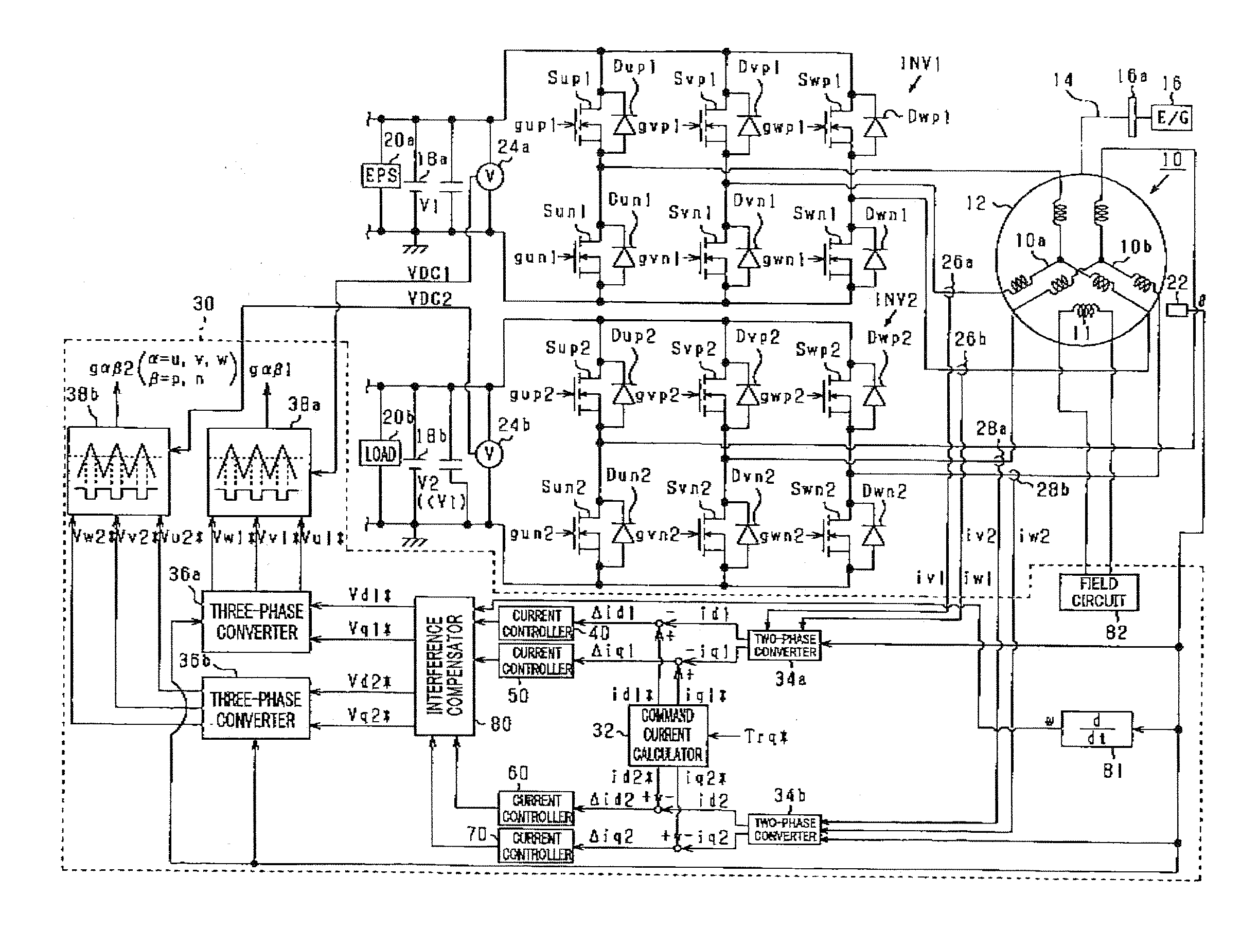
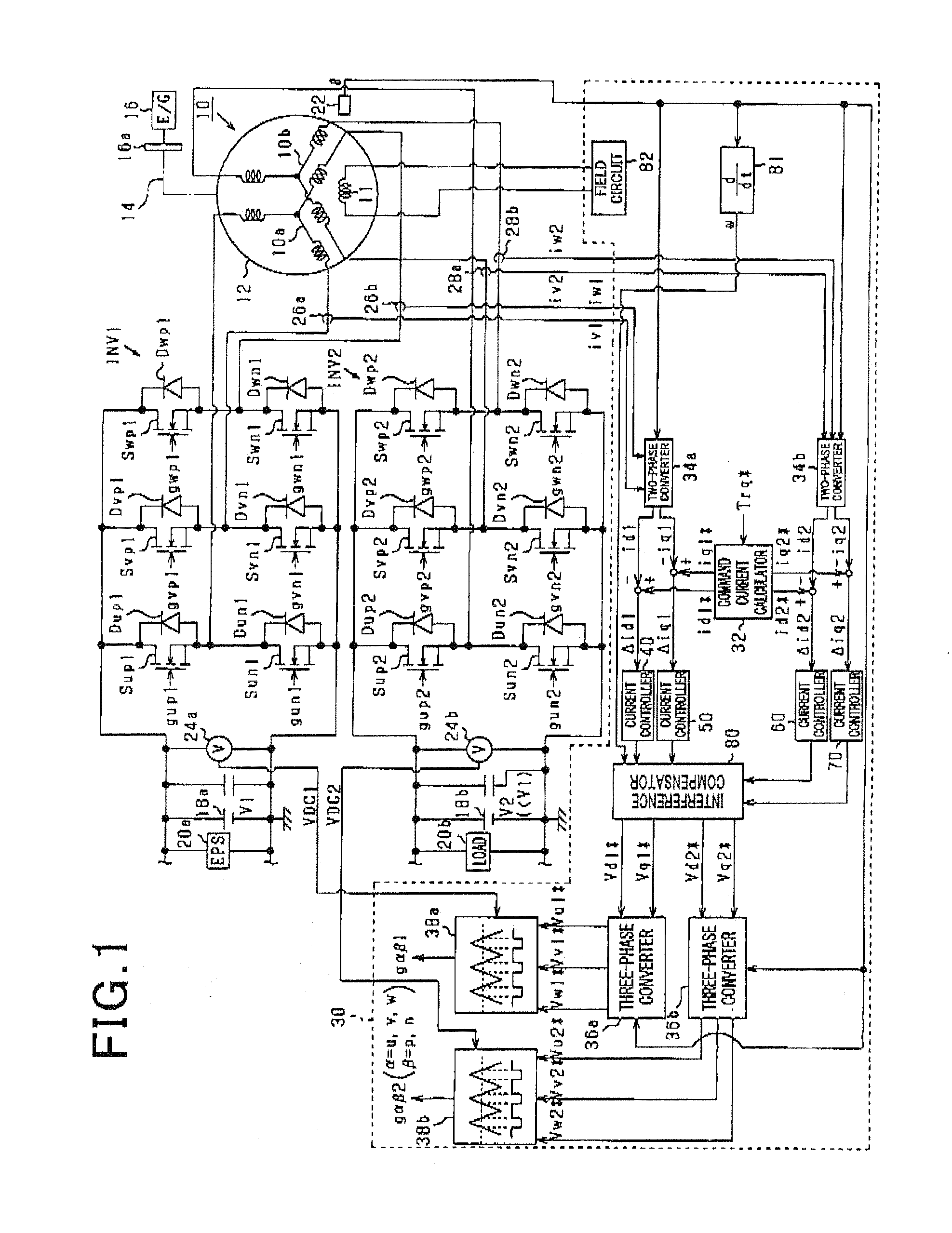
[0026]As shown in FIG. 1, a motor 10 is a three-phase double winding rotary machine, more specifically, a wound-field synchronous electrical motor. In the present embodiment, the motor 10 may be an integrated starter generator (ISG) that functions both as a starter and an alternator. A rotor 12 of the motor 10 includes field windings 11. Power transmission is enabled between the rotor 12 and a crankshaft 16a of an engine 16. In the present embodiment, the rotor 12 is connected to a crankshaft 16a via a belt 14.

[0027]A stator of the motor 10 includes two sets of three-phase windings: a first winding set 10a and a second winding set 10b. The first and second winding sets 10a, 10b have respectively different neutral points.

[0028]Two inverters, one...

second embodiment

[0085]There will now be explained a second embodiment of the present invention. Only differences of the second embodiment from the first embodiment will be explained.

[0086]In the present embodiment, the interference compensator 80 is modified in configuration as follows.

[0087]FIG. 9 shows a schematic block diagram of a current control system for the motor 10 of the present embodiment. Elements having similar functions as in the first embodiment are assigned the same numbers.

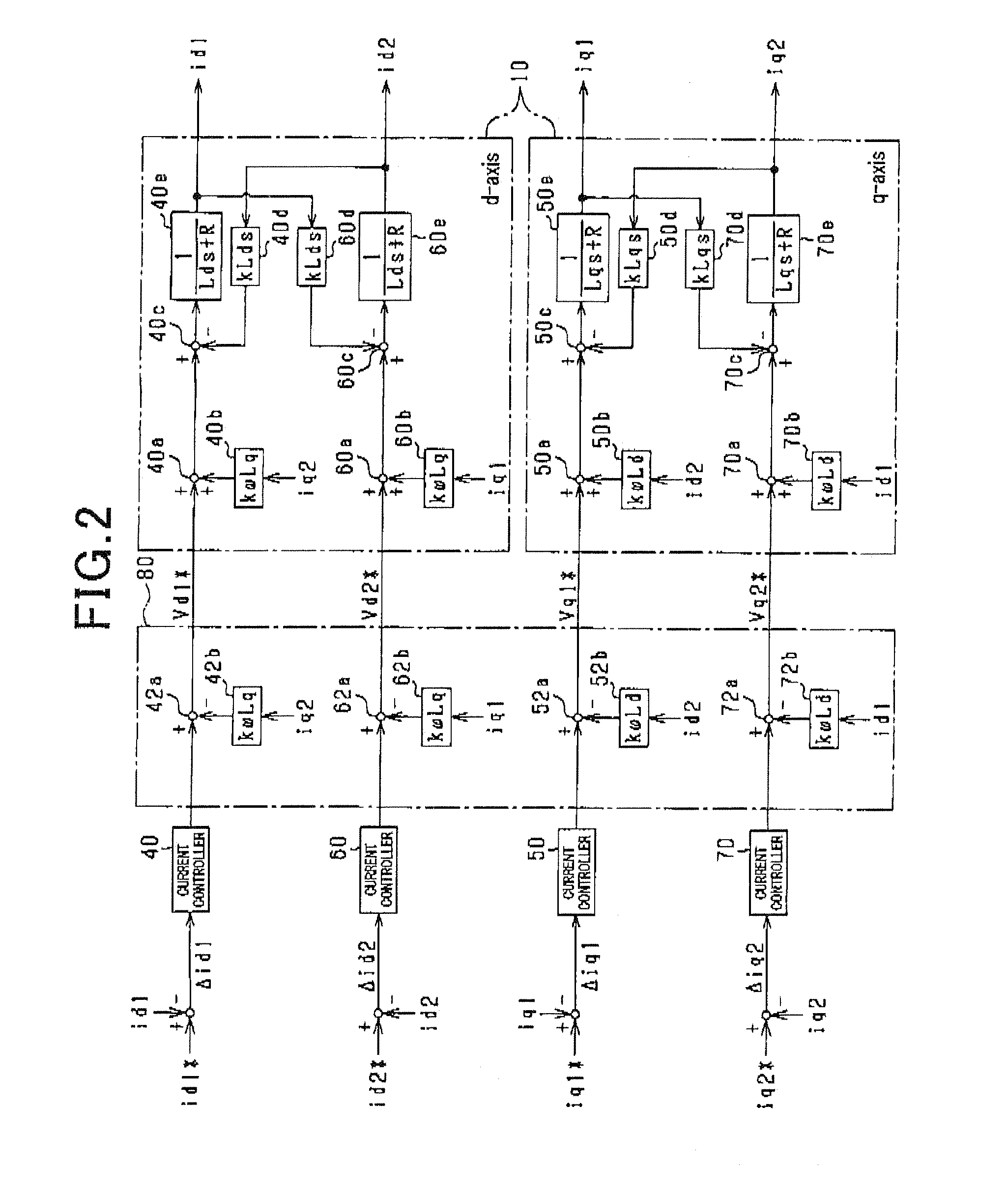
[0088]In the present embodiment, the first d-axis current controller 40 calculates a current value as a manipulated variable to feedback control the first d-axis current id1 to the first d-axis command current id1*. The first d-axis command voltage is calculated by inputting the current value calculated in first d-axis current controller 40 into a transfer function 42c that represents the impedance for the d-axis of the motor 10. Similarly, the second d-axis current controller 60 calculates a current value as a m...

third embodiment

[0095]There will now be explained a second embodiment of the present invention. Only differences of the third embodiment from the second embodiment will be explained.

[0096]In the present embodiment, the interference compensator 80 is further modified in configuration as follows.

[0097]FIG. 12 shows a schematic block diagram of a current control system for the motor 10 of the present embodiment. Elements having similar functions as in the second embodiment (see FIG. 9) are assigned the same numbers.

[0098]In the present embodiment, the command voltages Vd1*, Vq1*, Vd2*, Vq2* are compensated not only for their respectively corresponding rotation speed interfering voltages, but also for their respectively corresponding derivative interfering voltages.

[0099]More specifically, a first d-axis derivative voltage compensator 42d sums a first d-axis derivative interfering voltage and a first d-axis command voltage outputted from the transfer function 42c to feed the summed value to the first d...


PUM


Abstract

An apparatus for controlling a multi-winding rotary machine including an armature formed of a plurality of winding sets. In the apparatus, a command voltage calculator calculates command voltages to be applied to each winding set so as to control currents detected by a current detector to their respectively corresponding command currents. An interfering voltage calculator calculates, for each of the winding sets, interfering voltages proportional to the rotation speed of the rotary machine. An interfering voltage compensator compensates, for each of the winding sets, the command voltages for their respectively corresponding interfering voltages. An operation unit operates a voltage applicator to apply output values of the interfering voltage compensator to each winding set.

Description

CROSS-REFERENCE TO RELATED APPLICATION[0001]This application is based on and claims the benefit of priority from earlier Japanese Patent Application No. 2013-6127 filed Jan. 17, 2013, the description of which is incorporated herein by reference.BACKGROUND[0002]1. Technical Field[0003]The present invention relates to an apparatus for controlling a multi-winding rotary machine including an armature formed of a plurality of winding sets.[0004]2. Related Art[0005]In a three-phase double winding rotary machine, which is a rotary machine having two sets of three-phase windings, an interfering voltage proportional to a derivative of a current flowing through one of the two three-phase winding sets is induced in the other one due to magnetic coupling between the two three-phase winding sets, which may reduce responsiveness of a current control system for an electrical motor. To overcome this drawback, there has been proposed in Japanese Patent Application Laid-Open Publication No. 2003-1535...

Claims


Application Information

Patent Timeline
Patent Type & Authority Applications(United States)
IPC IPC(8): H02P6/00H02P21/00H02P21/22H02P27/04H02P27/08
CPCH02P6/002H02P6/28H02P25/22H02P27/08
Inventor ISHIDA, JUNTAKAHASHI, TOMOYA
Owner DENSO CORP
Why Eureka
Try Eureka