
Image processing apparatus, image pickup apparatus, and storage medium

a technology of image processing and image pickup, which is applied in the field of color image generation, can solve the problems of inability to perform real-time processing, large processing time, and inability to achieve real-time processing, and achieve the effects of reducing processing time, reducing processing time, and improving processing efficiency

Active Publication Date: 2014-10-23
CLARION CO LTD
View PDF2 Cites 50 Cited by
  • Summary
  • Abstract
  • Description
  • Claims
  • Application Information

AI Technical Summary

Benefits of technology

The invention aims to provide a technology that can capture color images with few blocked-up colors or low color saturation even when photographing subjects with high contrast. This results in faster processing and lower information processing amounts. The technology can be implemented using lower performance processors and higher speed image generating processing.

Problems solved by technology

When the division ( / ) and multiplication (×) are processed in a software manner by a processor (central processing unit; CPU) having low computing power, much time is necessary for processing, which causes a problem in that, for example, real-time processing cannot be performed, the number of image frames per unit time (for example, per second) needs to be reduced, or precision of another arithmetic operation (for example, image recognition processing) needs to be lowered.
Alternatively, when a processor having high computing power or dedicated hardware is used, a cost of an entire apparatus increases.

Method used


Image

  • Image processing apparatus, image pickup apparatus, and storage medium
  • Image processing apparatus, image pickup apparatus, and storage medium
  • Image processing apparatus, image pickup apparatus, and storage medium

Examples


first embodiment

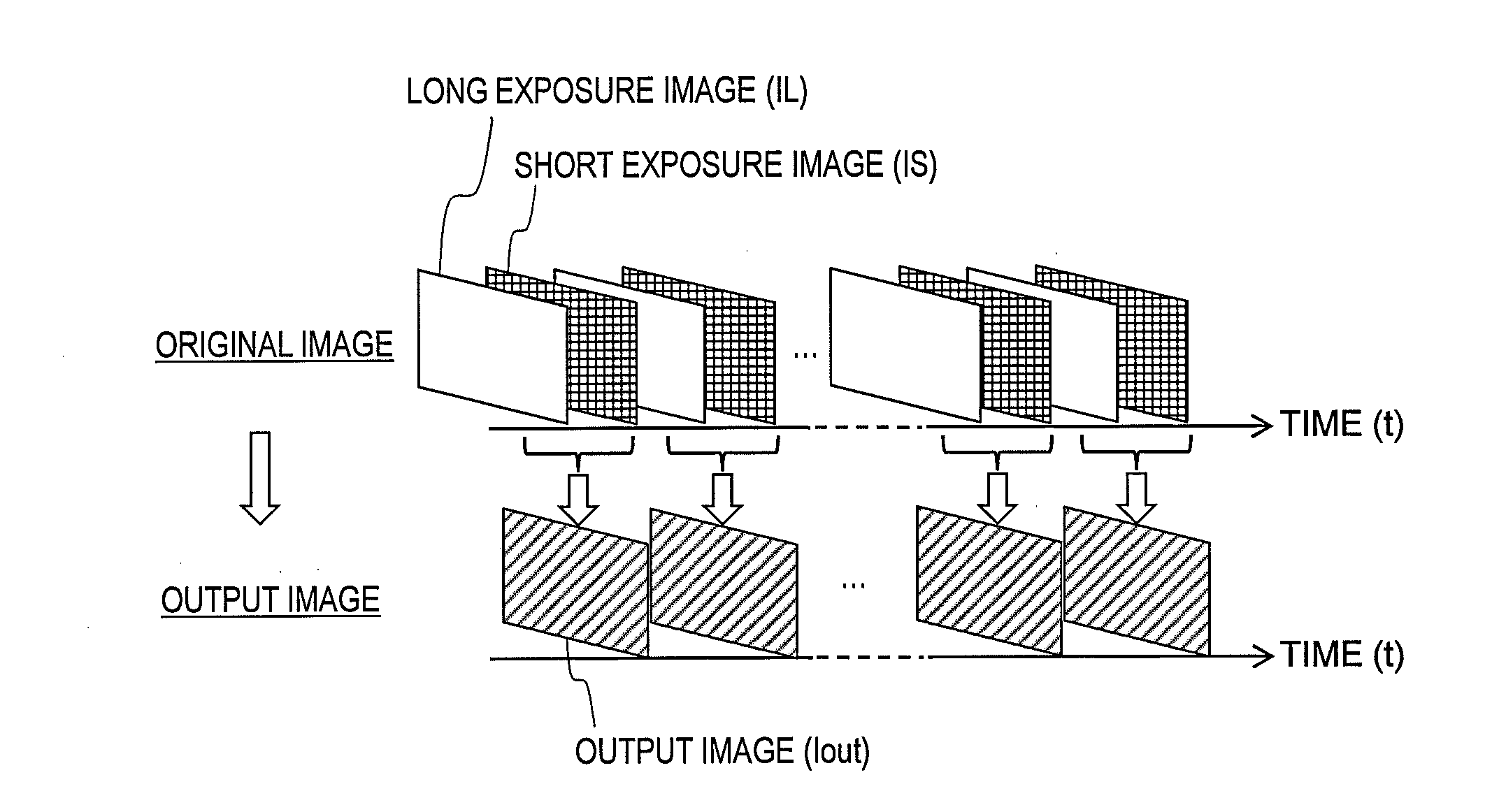
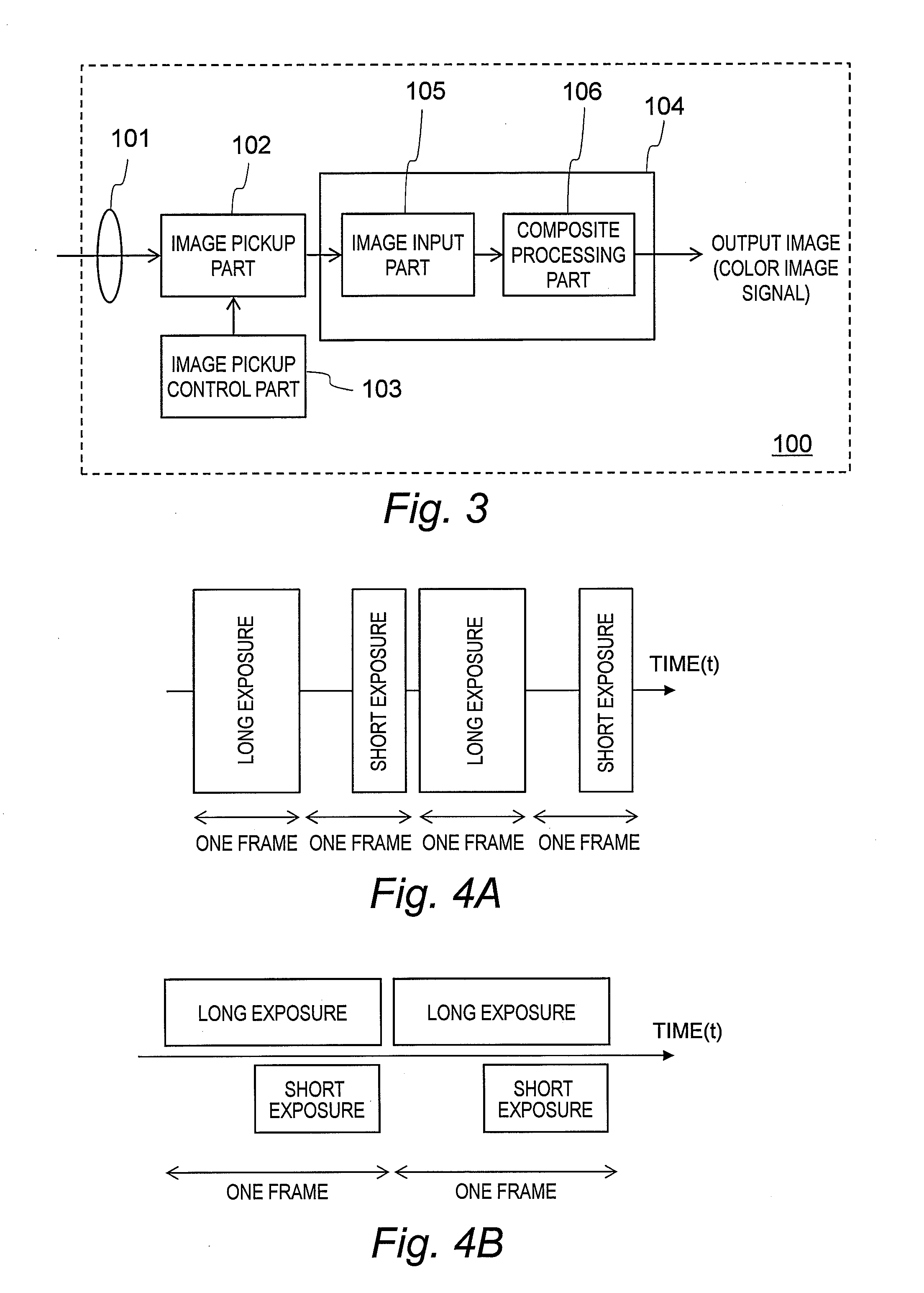
[0030]FIG. 3 is a block diagram illustrating an example in which an image processing apparatus 104 according to a first embodiment of this invention is included in an image pickup apparatus 100. The image pickup apparatus 100 includes a photographing lens 101, an image pickup part 102, an image pickup control part 103, and the image processing apparatus 104. The image processing apparatus 104 includes an image input part 105 and a composite processing part 106. The following description is made on the assumption that the above-mentioned components are integrally formed, but a camera unit formed of the photographing lens 101, the image pickup part 102, and the image pickup control part 103 may be formed separately from the image processing apparatus 104. The photographing lens 101 may be fixed to the camera unit, or may be removably mounted to the camera unit so as to be interchangeable to any one of various types of photographing lens depending on the purpose. The image processing a...

second embodiment

[0065]FIG. 8 illustrates an operation of a composite processing part 106A-1 of an image processing apparatus according to a second embodiment of this invention, and features thereof are described. The other components are the same as those described in the first embodiment, and hence descriptions thereof are omitted.

[0066]FIG. 8 is, similarly to FIG. 6, a diagram conceptually illustrating how the output image (Iout) is generated from the long exposure image (IL) and the short exposure image (IS). In FIG. 8, the pixel values (UL,VL) extracted from the long exposure image (IL) and the pixel values (US,VS) extracted from the short exposure image (IS) are compared with each other by the composite processing part 106A-1 between the pixel values UL and US and between the pixel values VL and VS. Then, the values having larger absolute values are selected to generate the pixel values UO and VO of the output image Tout. This point is the same as the processing performed by the composite proc...


PUM


Abstract

To generate a color image exhibiting few blocked-up colors or little color saturation. It is provided a image processing apparatus for processing an original image that is picked up, comprising: an image input part for inputting N original images having different exposure levels, where N is an integer of two or more, which are obtained by picking up images of the same subject in one of a simultaneous manner and a time-series manner; and a composite processing part for generating M output images, where M is an integer of one or more and less than N, by composing the N original images. The composite processing part compares color component signals in each corresponding pixel position with each other between the N original images, and sets the color component signal that produces a higher chroma as a color component signal in each pixel position of the output image.

Description

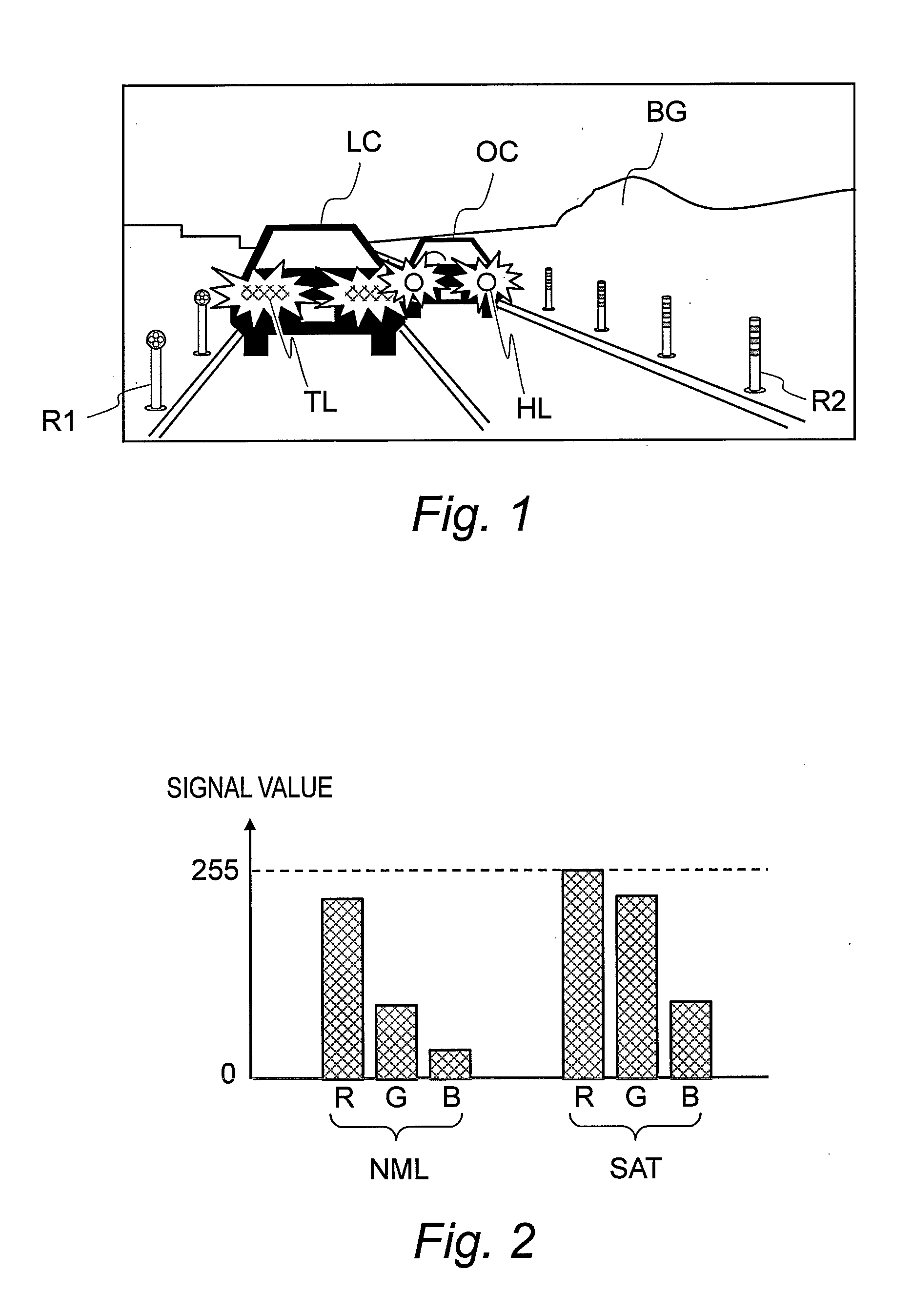
CLAIM OF PRIORITY[0001]The present application claims priority from Japanese patent application JP 2011-240672 filed on Nov. 1, 2011, the content of which is hereby incorporated by reference into this application.BACKGROUND OF THE INVENTION[0002]This invention relates to a technology for generating a color image.[0003]In recent years, research and development have been actively carried out in order to photograph a nighttime scene with an on-vehicle camera, a surveillance camera, or the like and make use thereof for safety and security of people's lives. Such a nighttime scene exhibits an extremely large contrast, and exceeds a limit of a dynamic range of a general image pickup element, which may generally cause a phenomenon called “blown-out highlights”, “blocked-up shadows”, or “color saturation”. In particular, in a case where a color (chromaticity) of a subject is used for image recognition processing or the like after photographing, when only a component of a specific color amon...

Claims


Application Information

Patent Timeline
Patent Type & Authority Applications(United States)
IPC IPC(8): H04N9/73H04N5/235H04N9/64
CPCH04N9/735H04N5/2355H04N9/646G06T11/001G06T5/50G06T2207/10016G06T2207/10024G06T2207/10144G06T2207/20012G06T2207/20221G06T2207/30232G06T2207/30252H04N9/77H04N23/741H04N25/581H04N25/587H04N23/843H04N25/134G06T5/90H04N23/95H04N23/86H04N9/68H04N25/58H04N23/80H04N23/88H04N23/743H04N25/583
Inventor KAGEYAMA, MASAHIROTAKAHASHI, TERUKITSUTSUI, TAKASHI
Owner CLARION CO LTD
Learn More