Active snubber topology

a topology and active technology, applied in the field of active snubber circuits, can solve the problems of high switching loss, direct and significant impact on the overall cost of the converter, and affect the electrical performance as well as the cost of the power converter

Active Publication Date: 2014-10-23
ABB E-MOBILITY BV
View PDF7 Cites 16 Cited by
  • Summary
  • Abstract
  • Description
  • Claims
  • Application Information

AI Technical Summary

Problems solved by technology

The switching frequency of a main switching device in a power converter can be a key parameter which affects the electrical performance as well as the cost of the power converter.
This reduction can have a direct and significant impact on the overall cost of the converter.
However, a large increase in the switching frequency of an existing power converter can include a trade-off.
For example, an increase from a few kHz to tens of kHz can result in very high switching losses.
Thus, the switching losses increase linearly with the switching frequency.
As a result, the power density and the power efficiency of the converter may degrade, and the cost savings gained in the magnetic parts may be nullified by the increased cooling system costs.
However, an additional resonant component and diode are connected in series with the main switch, which can increase the conducting state losses.
Moreover, the main switch may suffer from either over-voltage or over-current stress.
Higher rating, in turn, may increase the cost of the switch.

Method used


Image

  • Active snubber topology
  • Active snubber topology
  • Active snubber topology

Examples


Embodiment Construction

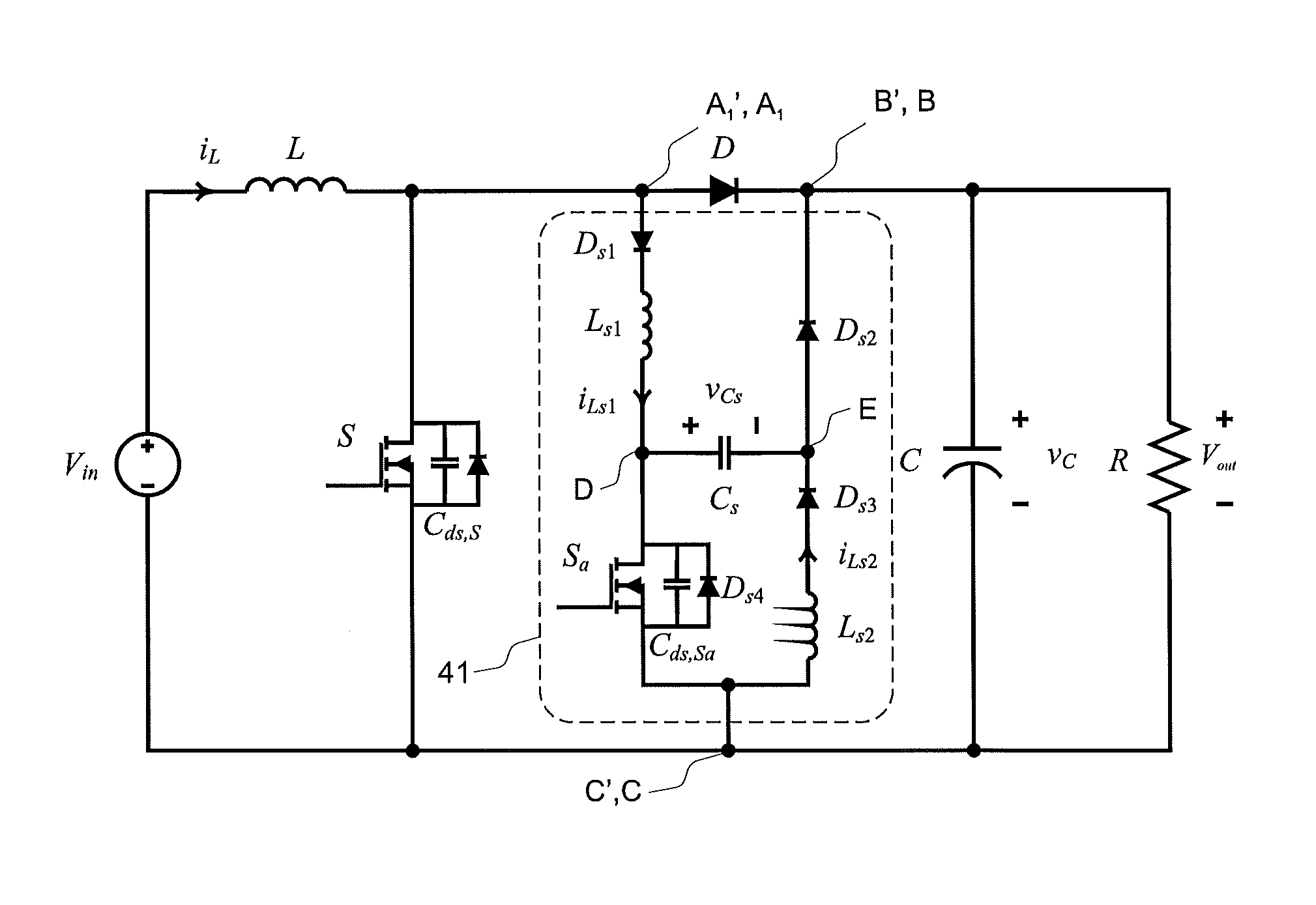
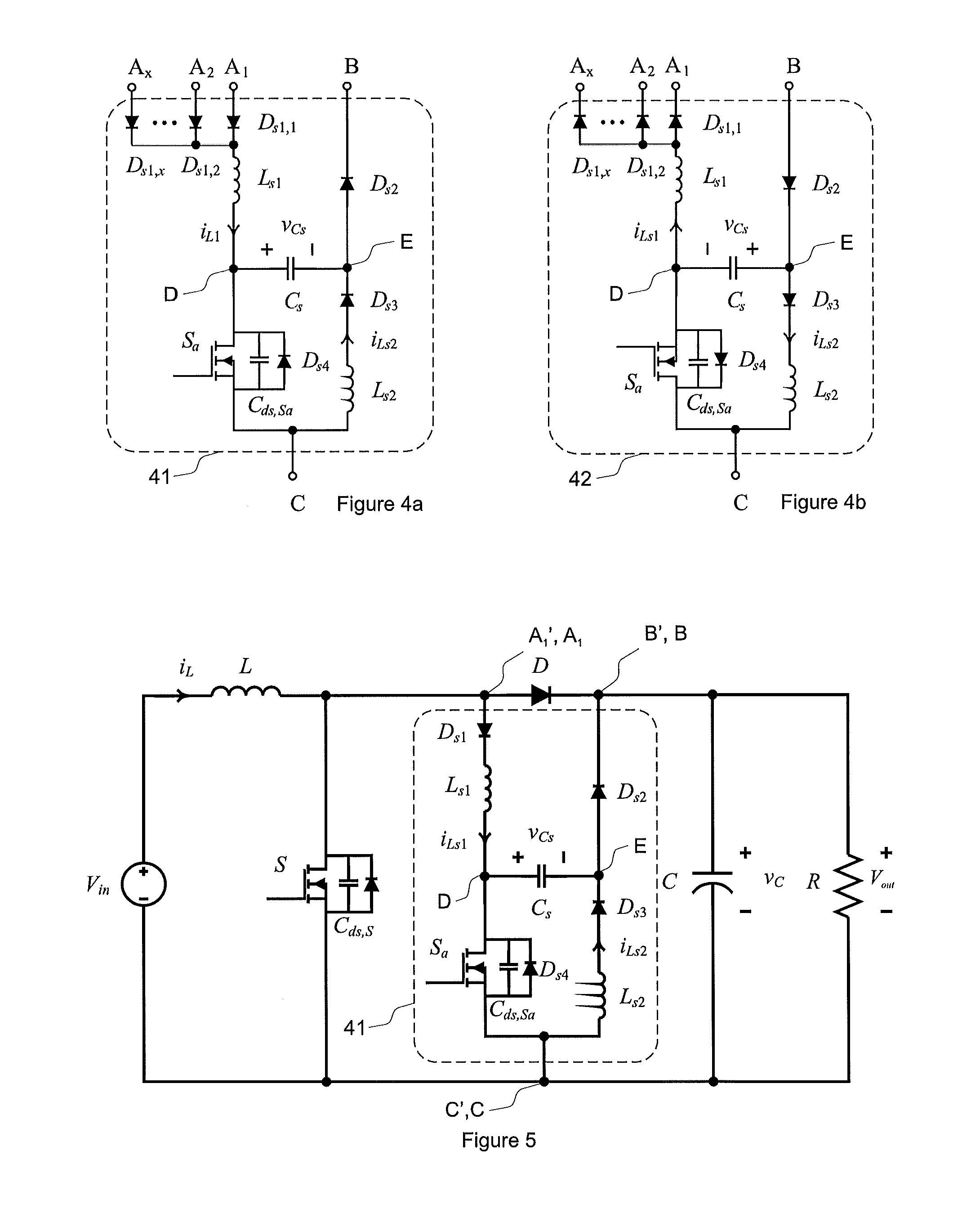
[0027]Exemplary embodiments of the present disclosure alleviate the disadvantages of known implementations by providing an active snubber topology which can reduce the switching losses of a main switch or main switches in a power converter. The active snubber includes an auxiliary switching device and modifies the switching trajectories of switching actions of the main switching device. The disclosed active snubber can assist the main switching device to perform turn-on and turn-off actions at zero-voltage. Switching losses can therefore be minimized.

[0028]The exemplary snubber described herein may be connected in parallel with the main switching device of the power converter. Thus, no series connection of a snubber inductor to the main switch or diode creating high conducting state losses is specified. The snubber topology of the present disclosure can have a very short operating time, for example less than 2 has, which minimizes conducting state losses in the snubber circuit. The ...


PUM


Abstract

Exemplary embodiments are directed to an snubber circuit and a power converter having an active circuit. The snubber circuit includes a series connection of a first diode and a first inductor connected between a first interfacing point and a first connection point, a second diode connected between a second connection point and a second interfacing point, a series connection of a third diode and a second inductor between a third interfacing point and the second connection point, a switching device connected between the first connection point and the third interfacing point, and a first capacitor connected between the first connection point and the second connection point. The first, the second, and the third diode are forward-biased along a path between the first interfacing point and the second interfacing point and through the third interfacing point.

Description

RELATED APPLICATION[0001]This application claims priority under 35 U.S.C. §119 to European Patent Application No. 13161957.9, filed in Europe on Apr. 2, 2013, the content of which is hereby incorporated by reference in its entirety.FIELD[0002]The present disclosure relates to power converters and particularly to snubber circuits for power converters.BACKGROUND INFORMATION[0003]The switching frequency of a main switching device in a power converter can be a key parameter which affects the electrical performance as well as the cost of the power converter. The size of passive elements, especially the magnetic elements, can be reduced by increasing the switching frequency of the converters. An input choke of a boost converter or an isolation transformer of a DC-DC converter can be used as examples of such magnetic elements. This reduction can have a direct and significant impact on the overall cost of the converter.[0004]Known power converter applications having cost-efficiency as the m...

Claims


Application Information

Patent Timeline
Patent Type & Authority Applications(United States)
IPC IPC(8): H02M1/34
CPCH02M1/34H02M1/342Y02B70/10
Inventor LI, TIN-HOHO, NGAI-MANESCOBAR, GERARDOBRADSHAW, JONATHAN
Owner ABB E-MOBILITY BV
Why Eureka
Try Eureka