DC-DC Converter and Power Conversion Apparatus

a technology of dc-dc converter and power conversion apparatus, which is applied in the direction of process and machine control, instruments, and semiconductor/solid-state device details, etc., can solve the problems of difficult inability to fabricate the switching element housing chassis, and inability to effectively diffuse heat, so as to improve the cooling efficiency of the switching element disposed outside the cooling range of a cooling channel, improve the heat dissipation ability of the radiator, and improve the thermal diffusion characteristi

Active Publication Date: 2014-10-23
HITACHI ASTEMO LTD
View PDF6 Cites 43 Cited by
  • Summary
  • Abstract
  • Description
  • Claims
  • Application Information

AI Technical Summary

Benefits of technology

[0011]According to the present invention, because the heat dissipation ability of the radiator is good, and there occur no large mixing phenomena of heat currents among neighboring switching elements, there are only little interferences among the neighboring switching elements. Therefore, because the thermal diffusion characteristic is improved, the cooling efficiency for the switching elements disposed outside the cooling range of a cooling channel can be increased.

Problems solved by technology

In the case where a thermal diffusion state generated by the switching elements H1 to H4 and the switching element IGBT is taken into consideration in such a configuration, because the switching elements H1 to H4 and the switching element IGBT are lying side-by-side, the switching elements generate large thermal interferences among themselves by generating heats, and the flows of the heats are mixed in adjacent spaces, with the result that it becomes difficult for the heats to be effectively diffused, and the heats are liable to accumulate.
In this case, it is not practical to fabricate the switching element housing chassis 43 with the same material as the material used for fabricating the radiator 41 because the fabrication cost of the switching element housing chassis 43 increases.
This is because components except for heat-generating components do not require much cooling capability, so that it is not advantageous to use an expensive material.

Method used


Image

  • DC-DC Converter and Power Conversion Apparatus
  • DC-DC Converter and Power Conversion Apparatus
  • DC-DC Converter and Power Conversion Apparatus

Examples


Embodiment Construction

[0027]Although the description of the embodiments of the present invention will be made hereinafter with reference to the accompanying drawings, the description will be made about two chapters: an explanation about the configuration of a power conversion apparatus as an example of power conversion apparatuses to which the present invention is applied is made in one chapter, and an explanation about a practical example of the present invention is made in the other chapter.

[0028]First, the mechanical configuration and circuit configuration of a power conversion apparatus to which the present invention is applied will be explained.

(Explanation about Mechanical and Circuit Configurations of Power Conversion Apparatus)

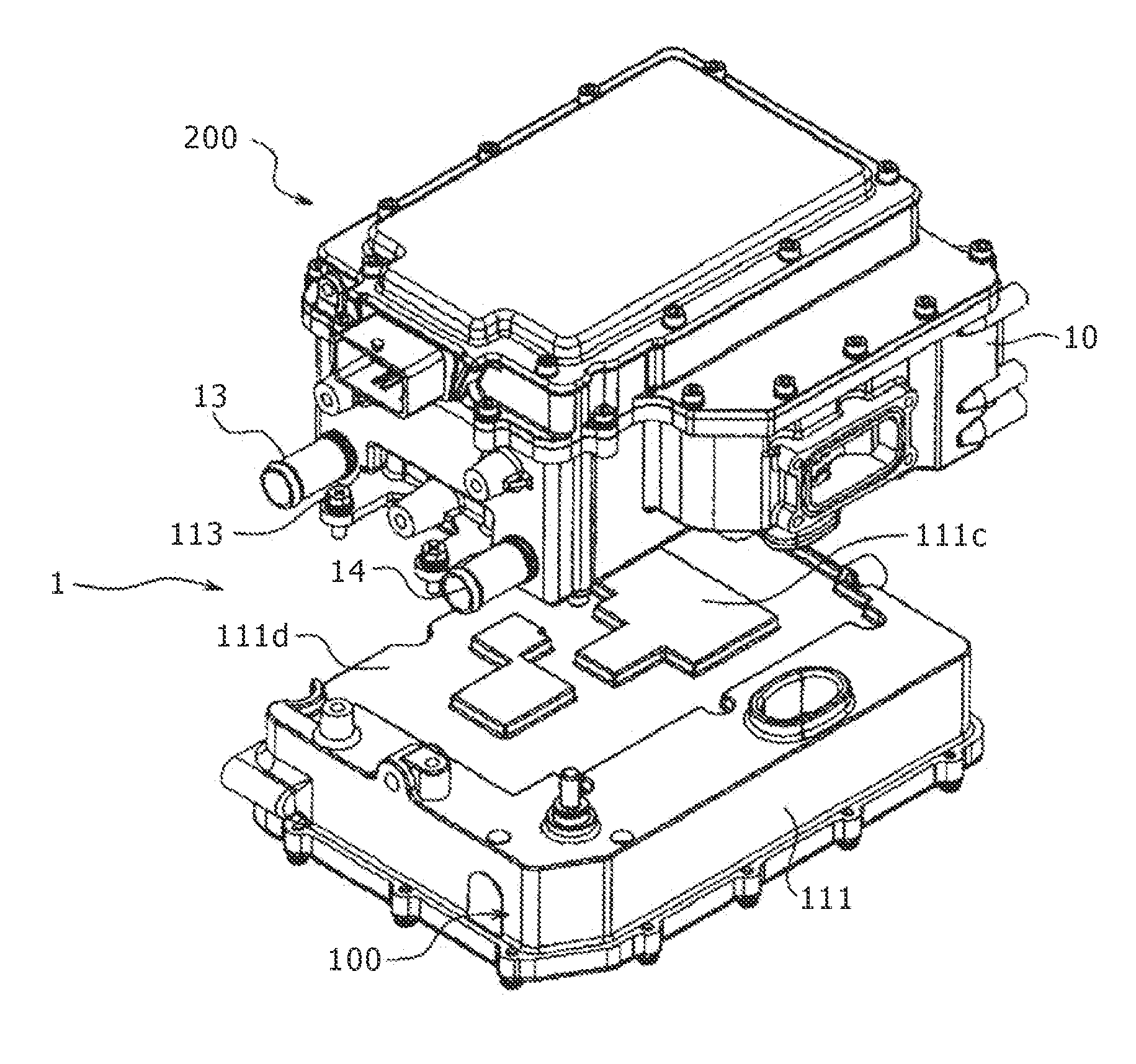
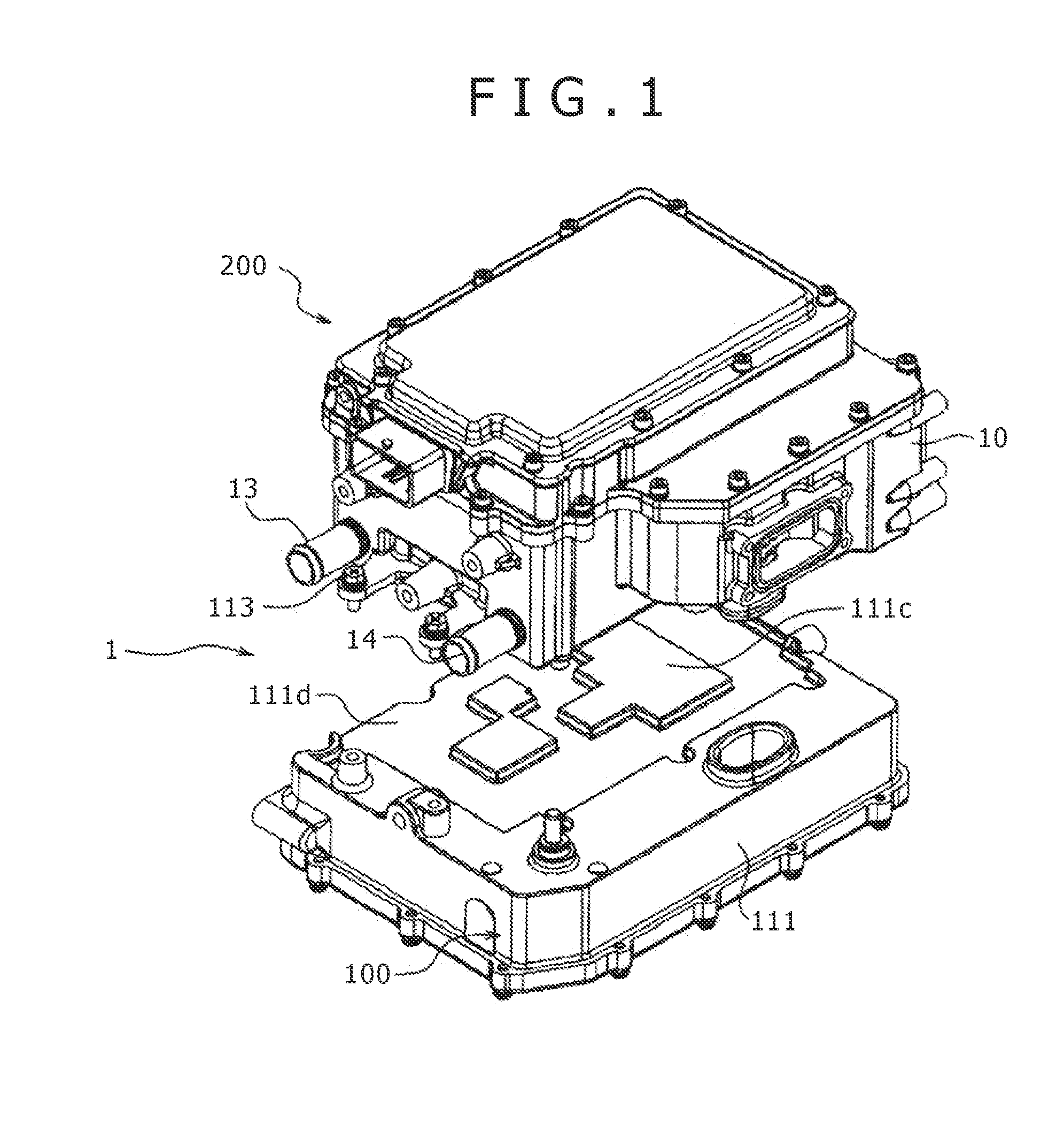
[0029]FIG. 1 and FIG. 2 are external perspective views of a power conversion apparatus 1, and the power conversion apparatus 1 is an integrated combination of a DC-DC converter 100 and an inverter 200. FIG. 1 and FIG. 2 respectively show the external perspective views in wh...


PUM


Abstract

In a DC-DC converter, the cooling of switching elements has been performed only by means of a cooling plate; therefore, there is a problem in that, to effectively radiate heats generated by power MOSFETs that have large heating values and that are arranged parallel, it becomes necessary to reduce thermal resistances and complicate the cooling route of a water-cooling device. Plural switching elements for controlling currents flowing through inductor elements, which are used for voltage conversion of a DC-DC converter, are fixed to a metal case via a heat conductive insulating material and via a metal radiator having a better heat conduction characteristic than the metal case. Because there occur no large mixing phenomena of heat currents among neighboring switching elements, and there are only little heat interferences between the neighboring switching elements, the thermal diffusion characteristic is improved, and the cooling efficiency for the switching elements can be increased.

Description

TECHNICAL FIELD[0001]The present invention relates to power conversion apparatuses for driving loads such as an electric motor, and in particular, relates to a power conversion apparatus that has improved cooling capability for cooling heat-generating components such as power converter elements included in a circuit system of a power conversion apparatus.BACKGROUND ART[0002]An electric vehicle or a plug-in hybrid vehicle is equipped with an inverter for driving a motor coupled to wheels with the use of a high voltage battery, and a low voltage battery for activating accessories such as vehicle lights, and a radio.[0003]On such a vehicle as above, a DC-DC converter that performs power conversion from a high voltage battery to a low voltage battery or from a low voltage battery to a high voltage battery is mounted.[0004]It is desirable that such a vehicle as above should have the ratio of the space of the vehicle room to the entire volume of the vehicle as large as possible in order t...

Claims


Application Information

Patent Timeline
Patent Type & Authority Applications(United States)
IPC IPC(8): H05K7/20H02M3/335
CPCH02M3/335H05K7/20H01L23/473H02M3/28H05K7/20927H01H9/52
Inventor SHINOHARA, HIDENORIYASUNAMI, MITSURUCHIDA, TADAHIKO
Owner HITACHI ASTEMO LTD
Why Eureka
Try Eureka