
Cover member, method and treatment module for treating a biological sample on a substrate

Active Publication Date: 2014-10-23
LEICA BIOSYST MELBOURNE
View PDF11 Cites 11 Cited by
  • Summary
  • Abstract
  • Description
  • Claims
  • Application Information

AI Technical Summary

Benefits of technology

The patent describes a device for handling fluids in a chamber with void walls that enhance fluid movement. The device has a fluid inlet and a cover member that can be opened and closed. The cover member also has guide means for sliding the substrate and is designed to prevent the sample from drying out. The technical effect of this invention is to provide a reliable and efficient tool for handling fluids in a chamber with reduced risk of drying out the sample.

Problems solved by technology

While automation has many advantages, there are also limitations associated with automating these procedures.
In some cases staining achieved by automated instrumentation is patchy or unreliable leading to rejection or “failure” of some slides by the pathologist.
Failure can be attributable to bubbles forming in the reagent which leads to uneven stains, and / or debris from reagents producing lower quality stains.
In other cases the cost to run each test is prohibitively high typically because of the high cost of purchasing and maintaining the instrumentation and / or the reagents used.
In other cases still, stained areas are too small relative to the sample size and are not useful for diagnostic analysis.
Complexity of the automated instrumentation can also be problematic with myriad moving parts requiring calibration, maintenance and cleaning.
In many cases processed sample throughput is limited by batch processing regimes where sample processing times are limited by the slowest staining protocol being administered in the batch.

Method used


Image

  • Cover member, method and treatment module for treating a biological sample on a substrate
  • Cover member, method and treatment module for treating a biological sample on a substrate
  • Cover member, method and treatment module for treating a biological sample on a substrate

Examples


Embodiment Construction

[0126]It is desirable to perform incubation of small volumes of reagents on a substrate such as a microscope slide. Samples may be treated while slides are retained in a slide tray or individually at sample treatment modules.

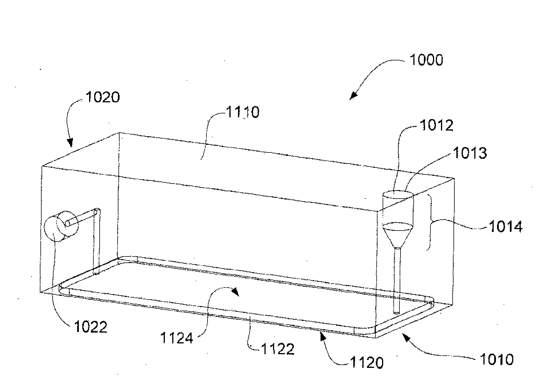
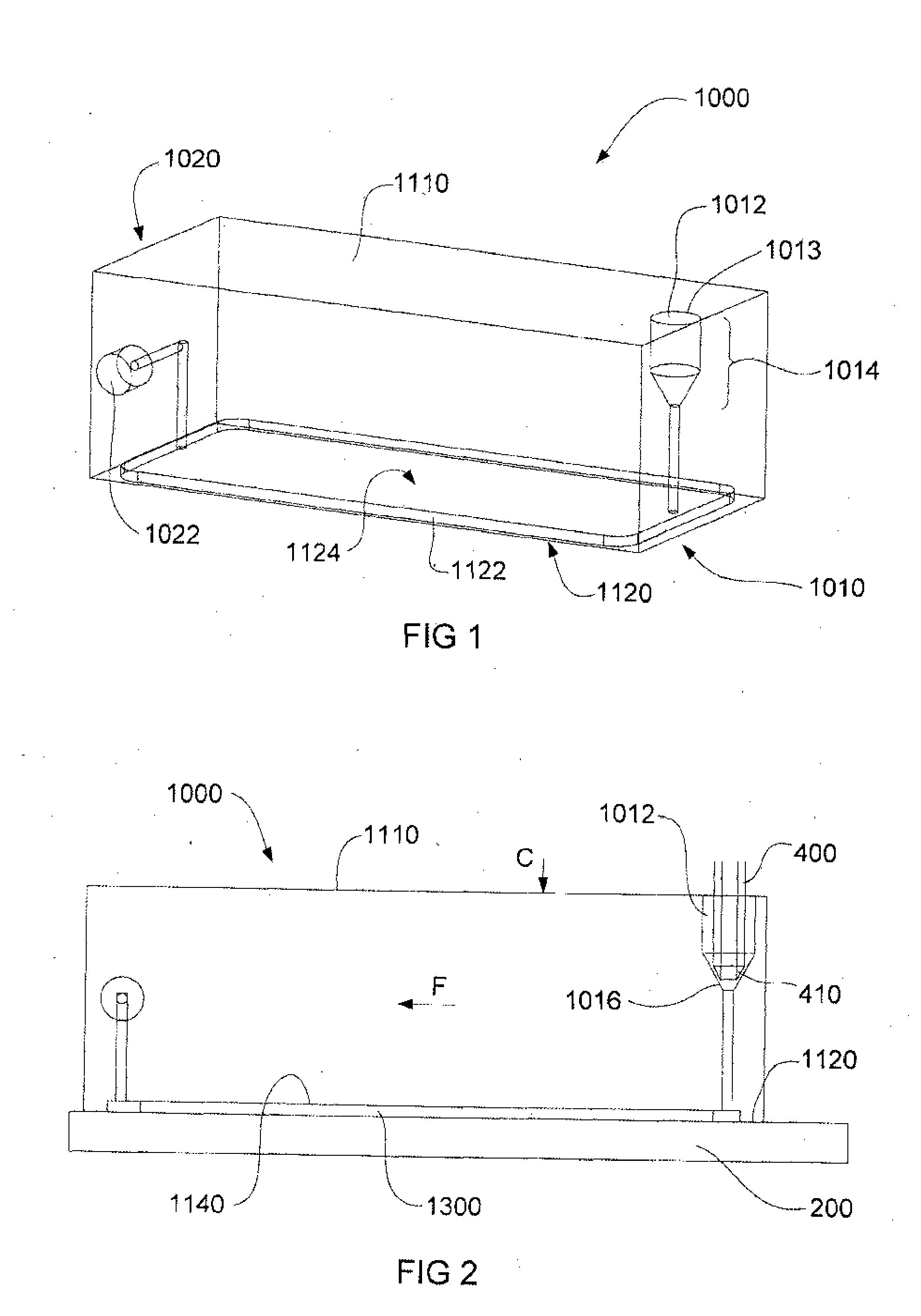
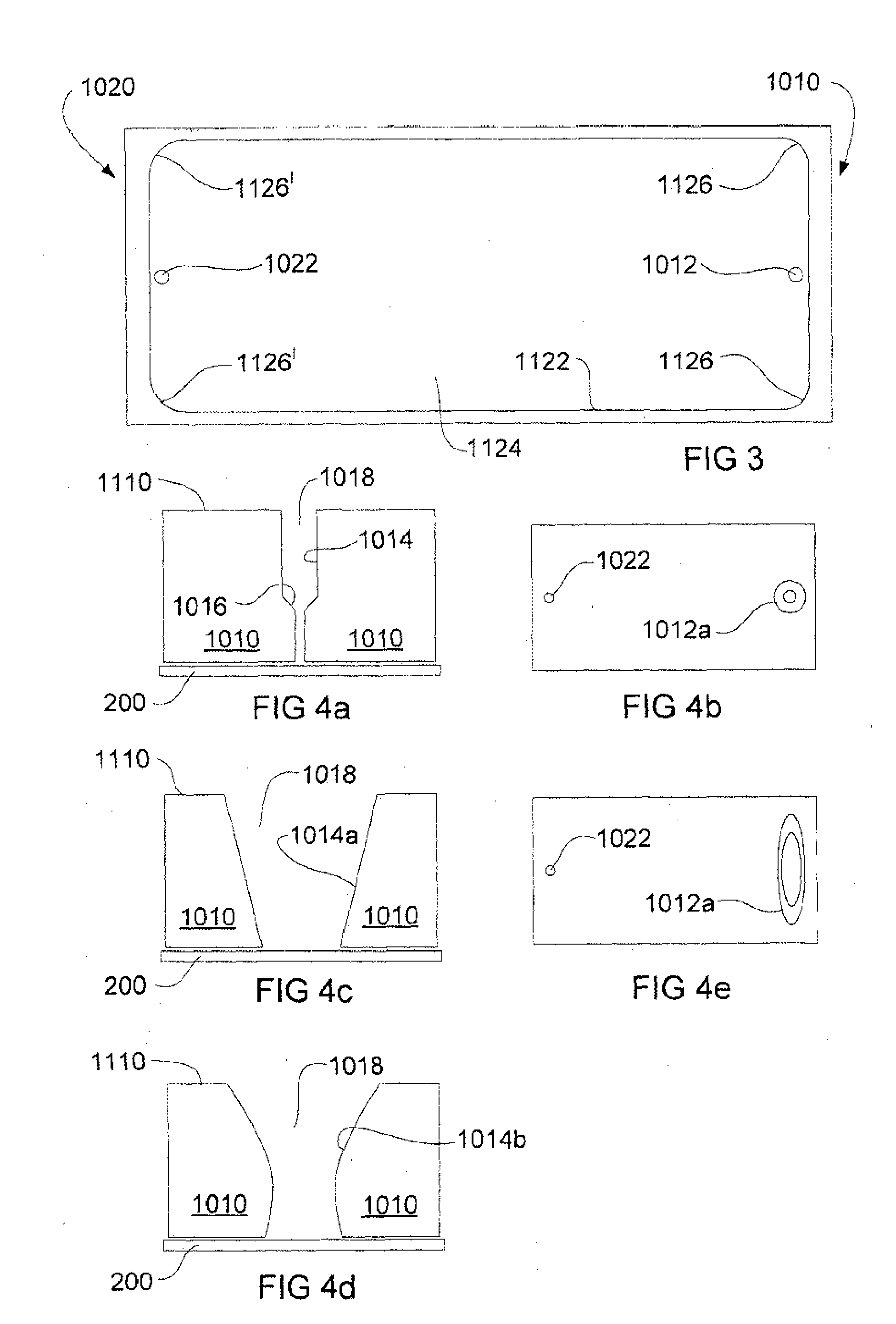
[0127]Referring firstly to FIG. 1, there is shown a cover member 1000 according to an embodiment of the invention, for use with a substrate 200 (shown in FIG. 2) for supporting a biological sample. For ease of reference, substrate 200 is hereinafter referred to as “slide”200. The cover member has a first end 1010 and a second end 1020 and a first surface 1110 and a second surface 1120. A void 1124 is formed in the second surface, defined by a void boundary in the form of walls 1122 and a void ceiling 1140.

[0128]FIG. 2 is a side sectional view of the cover member 1000 and slide 200 disposed in juxtaposition to form a chamber 1300. A fluid inlet 1012 is provided toward the first end of the cover member and a fluid outlet 1022 is provided toward the second end of t...


PUM


Abstract

A cover member for a substrate supporting a biological sample comprises first and second opposing ends, first and second opposing surfaces, a void in the second surface which, when juxtaposed with a substrate, forms a chamber, and a fluid inlet toward the first end and in fluid communication with the void. The void is bounded by void walls having one or more contoured regions for enhancing fluid movement within the chamber. A treatment module for a biological sample comprises the cover member, a support surface for a substrate bearing the biological sample and clamp means operable to releasably retain the cover member in juxtaposition with the substrate for an incubation period. A method for incubating the biological sample with one or more reagents uses the cover member.

Description

FIELD OF THE INVENTION[0001]This invention relates to instrumentation and methods for automated staining of anatomical pathology samples. It relates particularly, but not exclusively to, a cover member which forms a reagent chamber over a substrate, such as a slide on which a pathology sample has been placed.BACKGROUND TO THE INVENTION[0002]Instrumentation for automated treatment of biological samples, such as anatomical pathology samples, is well known. Treatment may include staining procedures of the kinds that are typical in immunochemistry, in-situ hybridisation, special staining and cytology. Automation of some staining procedures has increased the speed with which pathology testing can be completed leading to earlier diagnosis and in some cases, intervention. Staining is typically performed on samples placed on microscopy slides to highlight certain histological features in a biological sample and incubation of the sample with small volumes of reagent is often performed. In ma...

Claims


Application Information

Patent Timeline
IPC IPC(8): B01L3/00
CPCB01L3/502G01N1/312B01L3/5027B01L7/52B01L9/527B01L2200/027B01L2200/0689B01L2300/0822B01L2300/0851B01L2300/0877B01L2300/1822B01L2300/1827B01L2300/1861B01L2300/1866Y10T436/25
Inventor DOCKRILL, MARK BRIANFAVALORO, ANTHONYNG, KENNETH HENG-CHONGLIMON, MARTINTOOGOOD, PETERBAGNATO, STEPHEN JOHN
Owner LEICA BIOSYST MELBOURNE
Learn More