
Construction machine

a construction machine and construction technology, applied in the direction of electrical control, exhaust treatment, separation process, etc., can solve the problems of deteriorating filter performance, increasing the frequency of regeneration treatment, increasing the amount of particulate matter emitted, etc., to prevent excessive engine or filter malfunction, reduce the effect of deterioration in durability and restricting large loads

Active Publication Date: 2014-10-30
NIHON KENKI CO LTD
View PDF8 Cites 15 Cited by
  • Summary
  • Abstract
  • Description
  • Claims
  • Application Information

AI Technical Summary

Benefits of technology

The present invention aims to provide a construction machine that can prevent the use of low-quality fuel or engine oil from damageing the filter or engine, ultimately improving reliability and stability. It does this by restricting the output of the engine in case of malfunction in the regeneration device, reducing the load on the engine and preventing deterioration in durability and excessive malfunction.

Problems solved by technology

When this fuel or engine oil of low quality is used, an emission amount of the particulate matter increases, which might possibly increase the frequency of the regeneration treatment and deteriorate performance of the filter.
Here, since the map is produced using fuel or engine oil of standard quality, when fuel or engine oil of low quality, for example, is used, there is a possibility that an error between the trapping amount to be estimated and an actual trapping amount becomes large.
When the engine continues to operate in a state where the error is large, the regeneration treatment is executed in a state where the particulate matter is excessively accumulated in the filter to excessively increase a temperature of the filter, thus possibly deteriorating durability of the filter.
Further, there is also a possibility of deteriorating durability of equipment configuring a fuel injection system of the engine and the like.
The conventional art according to Patent Document 4 is configured such that the regeneration treatment is executed by considering ashes accumulated in the filter as well, but has a possibility of being incapable of sufficiently ensuring estimation accuracy of the ash.
Particularly this conventional art cannot cope with varying factors generated in a case where the fuel or engine oil of low quality is temporarily used, which might possibly deteriorate durability of the filter or the engine as similar to the conventional art by Patent Document 2.

Method used


Image

  • Construction machine
  • Construction machine
  • Construction machine

Examples


first embodiment

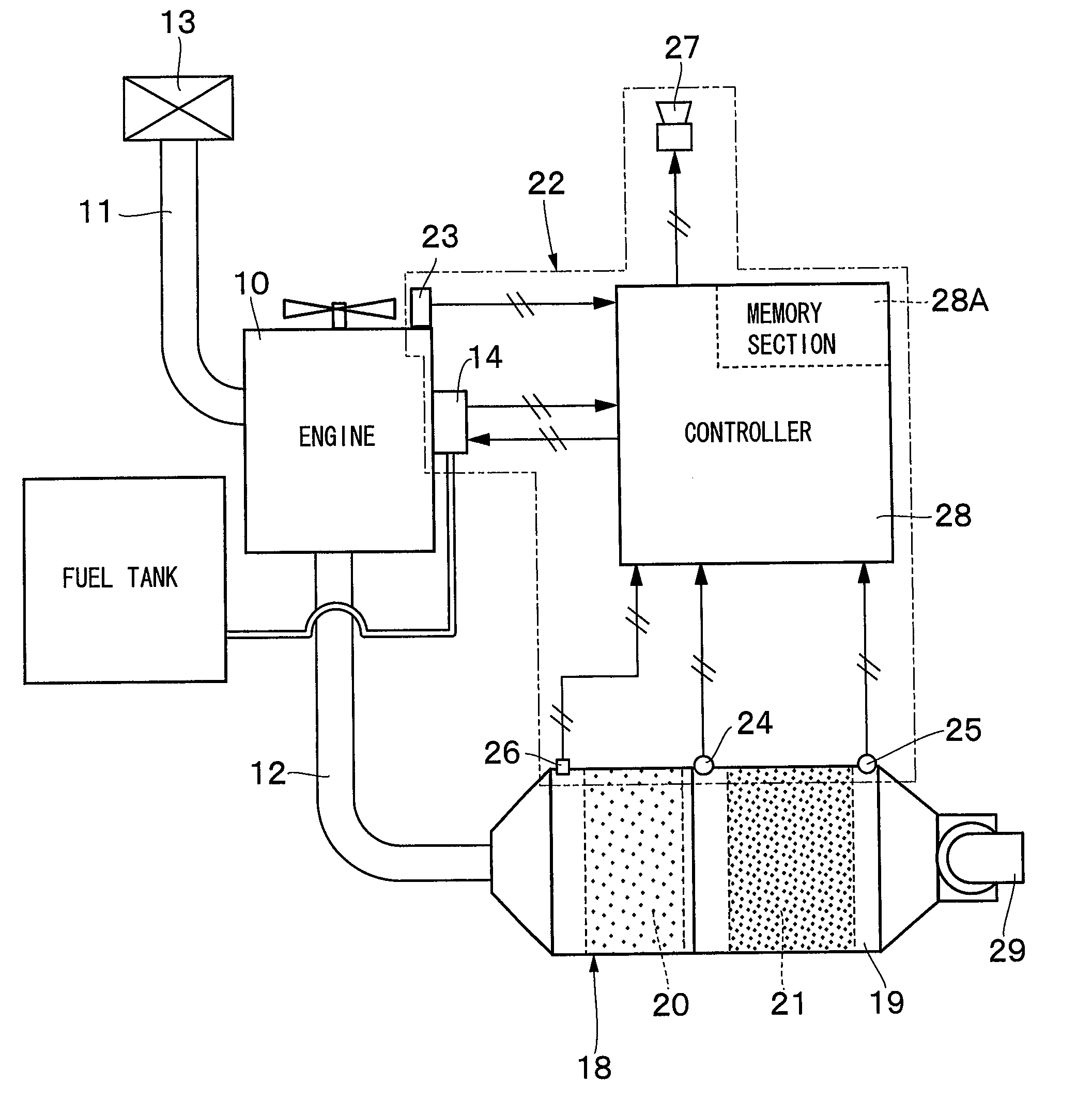
[0044]FIG. 1 to FIG. 6 show a construction machine according to the present invention.

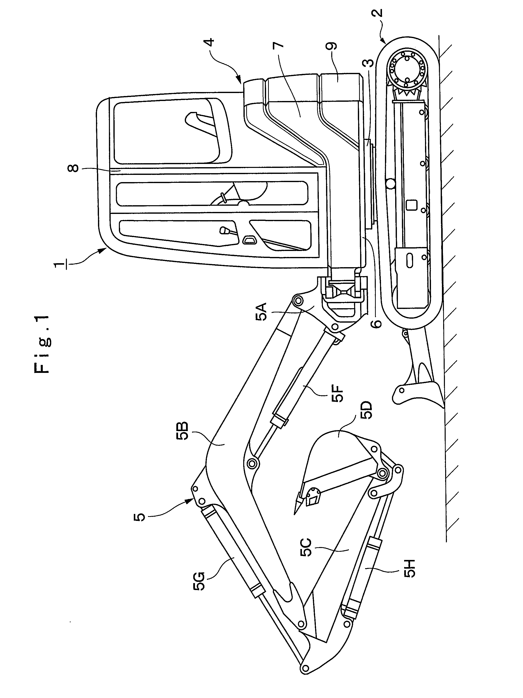
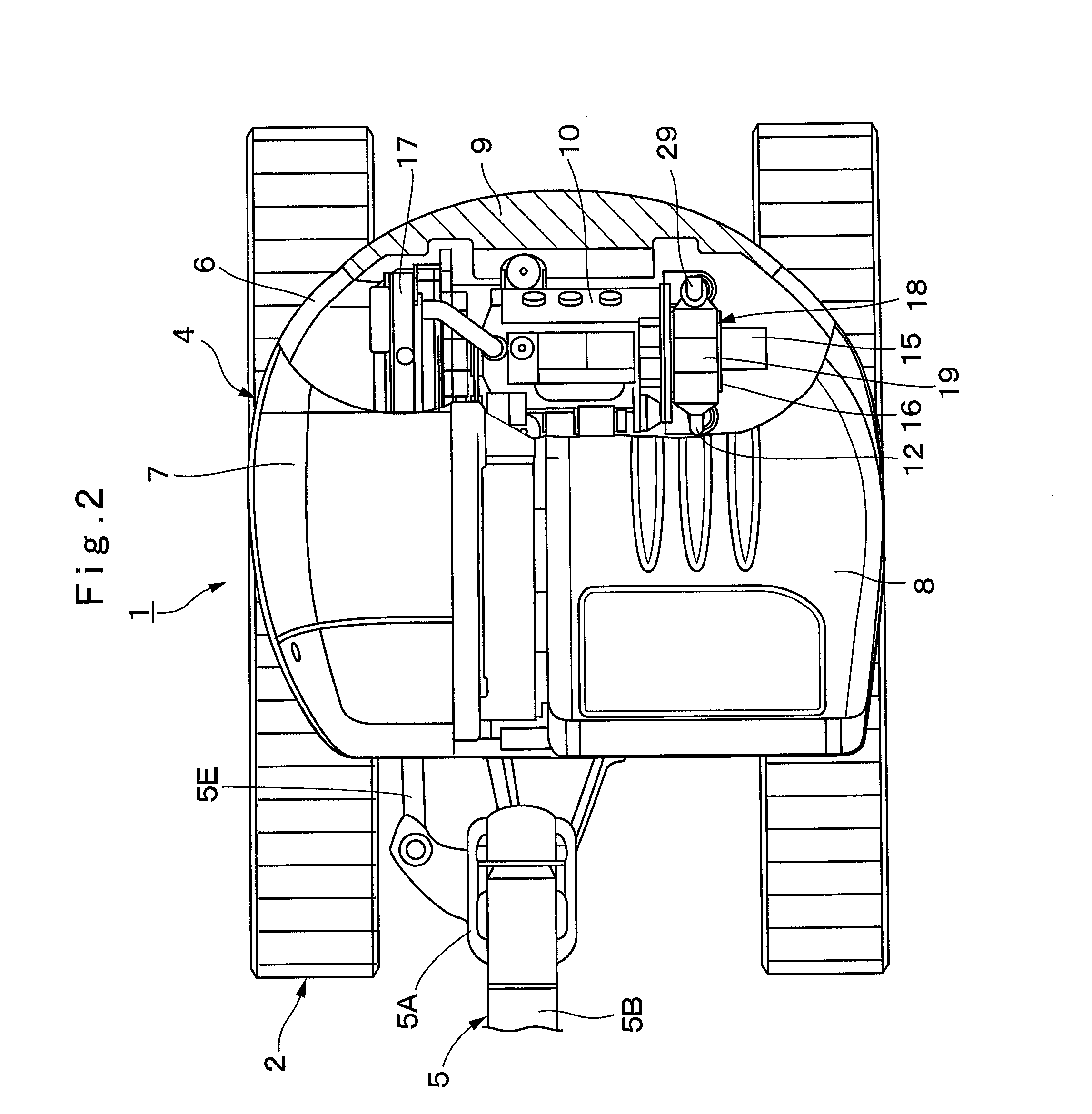
[0045]In the figure, designated at 1 is a small-sized hydraulic excavator used for an excavating work of sand and earth or the like. The hydraulic excavator 1 is configured schematically by a crawler type of automotive lower traveling structure 2, an upper revolving structure 4 that is mounted through a revolving device 3 on the lower traveling structure 2 to be capable of revolving thereon and configures a vehicle body together with the lower traveling structure 2, and a working mechanism 5 that is tiltably provided in a front side of the upper revolving structure 4.

[0046]Here, the working mechanism 5 is formed as a swing post type working mechanism, and is provided with, for example, a swing post 5A, a boom 5B, an arm 5C, a bucket 5D as a working tool, a swing cylinder 5E (refer to FIG. 2) for swinging the working mechanism 5 in the left-right direction, a boom cylinder 5F, an arm cylinder 5G, an...

second embodiment

[0108]The malfunction determining process is also a process for determining whether or not there is the malfunction in the regeneration device 22 or the engine 10 by using the first estimated trapping amount Q1 estimated at step 3 and the second estimated trapping amount Q2 estimated at step 6. In a case where it is determined that there is the malfunction, the alarm that there is the malfunction is given to an operator and the process of restricting the output of the engine 10 to be smaller than in a case where there is no malfunction is executed.

[0109]That is, at step 21, as similar to step 11 in the first embodiment, it is determined whether or not the second estimated trapping amount Q2 is larger than the first estimated trapping amount Q1 (Q121, a determination of “YES” is made, that is, it is determined that the second estimated trapping amount Q2 is larger than the first estimated trapping amount Q1, the routine goes to step 23, wherein it is determined whether or not the in...

third embodiment

[0121]Particularly, in a case of the third embodiment, since the regeneration treatment is executed by operating at least one of the intake throttle valve 32 and the exhaust throttle valve 33 in the direction of throttling the flow passage, the regeneration treatment can be executed at a lower temperature as compared to a case of executing the regeneration treatment by the post injection. Thereby, durability of the filter 21 can be improved.

[0122]Next, FIG. 10 and FIG. 11 show a fourth embodiment in the present invention. The fourth embodiment is characterized by making a determination on the malfunction based upon a difference (ΔQ=Q2−Q1) between a first estimated trapping amount (Q1) and a second estimated trapping amount (Q2), an interval (ΔL) of the regeneration treatment executed in a state where the difference (ΔQ) is equal to or more than a predetermined value (ΔQs), and the number of times (M) of the regeneration treatment. It should be noted that in the fourth embodiment, co...


PUM

PropertyMeasurementUnit
rotational speedaaaaaaaaaa
pressureaaaaaaaaaa
thresholdaaaaaaaaaa

Abstract

A regeneration device that performs regeneration treatment of a particulate matter removing filter estimates a trapping amount of particulate matter trapped in the filter by two systems. Specifically, there are provided an estimating unit that estimates a first estimated trapping amount based upon a rotational speed of an engine and a fuel injection quantity and an estimating unit that estimates a second estimated trapping amount based upon a differential pressure across the particulate matter removing filter. The regeneration device determines whether or not the regeneration treatment is executed based upon whether or not at least one of the two estimated trapping amount is equal to or more than a preset trapping amount threshold value. Further, the regeneration device determines that there is a malfunction in the regeneration device in a case where the second estimated trapping amount is larger than the first estimated trapping amount.

Description

TECHNICAL FIELD[0001]The present invention relates to a construction machine that is provided with an exhaust gas purifying device suitable for removing harmful substances from an exhaust gas in a diesel engine, for example, or the like.BACKGROUND ART[0002]A construction machine such as a hydraulic excavator or a hydraulic crane is generally configured by an automotive lower travelling structure, an upper revolving structure mounted on the lower travelling structure to be capable of revolving thereon, and a working mechanism tiltably mounted on a front side of the upper revolving structure. The upper revolving structure mounts an engine on a rear portion in a revolving frame for driving a hydraulic pump, and mounts a cab, a fuel tank, an operating oil tank and the like on a front side in the revolving frame.[0003]Here, a diesel engine is generally used as an engine that is a prime mover of a hydraulic excavator. There are some cases where harmful substances such as particulate matte...

Claims


Application Information

Patent Timeline
Patent Type & Authority Applications(United States)
IPC IPC(8): F01N11/00F01N3/023B60K13/04
CPCF01N11/002F01N3/023B60K13/04B01D46/0086E02F3/325E02F9/0866E02F9/2066E02F9/2095E02F9/267F01N3/0235F01N9/002F01N11/00F01N13/008F01N2240/36F01N2550/04F01N2560/06F01N2560/08F01N2560/14F01N2590/08F01N2900/0412F01N2900/0422F01N2900/08F01N2900/1606F02D41/0235F02D41/0245F02D41/029F02D41/1448F02D41/405F02D2041/227F02D2041/228F02D2200/0614F02D2200/0812F02D2200/101Y02T10/40
Inventor NOGUCHI, SHUUHEIYOSHIDA, HAJIME
Owner NIHON KENKI CO LTD
Learn More