Passive reactor cooling system

a reactor and cooling system technology, applied in nuclear engineering, nuclear elements, greenhouse gas reduction, etc., can solve the problems of rapid rise of pressure and temperature in the containment space, exponential cooling of decay heat, and reactors into scraps, so as to prevent warping

Active Publication Date: 2014-10-30
SMR INVENTEC
View PDF4 Cites 9 Cited by
  • Summary
  • Abstract
  • Description
  • Claims
  • Application Information

AI Technical Summary

Benefits of technology

[0016]Embodiments of the system may further include an auxiliary air cooling system including a plurality of vertical inlet air conduits spaced circumferentially around the containment vessel in the annular reservoir. The air conduits are in fluid communication with the annular reservoir and outside ambient air external to the containment enclosure structure (CES). When a thermal energy release incident occurs inside the containment vessel and water in the annular reservoir is substantially depleted by evaporation, the air cooling system becomes operable by providing a ventilation path from the reservoir space to the external ambient. The ventilation system can thus be viewed as a secondary system that can continue to cool the containment ad infinitum.
[0017]According to another embodiment, a nuclear reactor containment system includes a containment vessel configured for housing a nuclear reactor, a containment enclosure structure (CES) surrounding the containment vessel, a water filled annulus formed between the containment vessel and containment enclosure structure (CES) for cooling the co...

Problems solved by technology

First, an event that follows a loss-of-coolant accident (LOCA) and involve a rapid large release of thermal energy from the plant's nuclear steam supply system (NSSS) due to a sudden release of reactor's coolant in the containment space.
The reactor coolant, suddenly depressurized, would violently flash resulting in a rapid rise of pressure and temperature in the containment space.
Another second thermal event of potential risk to the integrity of the containment is the scenario wherein all heat rejection paths from the plant's nuclear steam supply system (NSSS) are lost, forcing the reactor into a “scram.” A station black-out is such an event.
Although its thick concrete wall could be capable of withstanding an ai...

Method used


Image

  • Passive reactor cooling system
  • Passive reactor cooling system
  • Passive reactor cooling system

Examples


Embodiment Construction

[0050]The features and benefits of the invention are illustrated and described herein by reference to illustrative embodiments. This description of illustrative embodiments is intended to be read in connection with the accompanying drawings, which are to be considered part of the entire written description. In the description of embodiments disclosed herein, any reference to direction or orientation is merely intended for convenience of description and is not intended in any way to limit the scope of the present invention. Relative terms such as “lower,”“upper.”“horizontal,”“vertical,”, “above,”“below,”“up,”“down,”“top” and “bottom” as well as derivative thereof (e.g., “horizontally,”“downwardly.”“upwardly,” etc.) should be construed to refer to the nominal orientation as then described or as shown in the drawing under discussion. These relative terms are for convenience of description only and do not require that the apparatus be constructed or operated in a rigorously specific ori...


PUM


Abstract

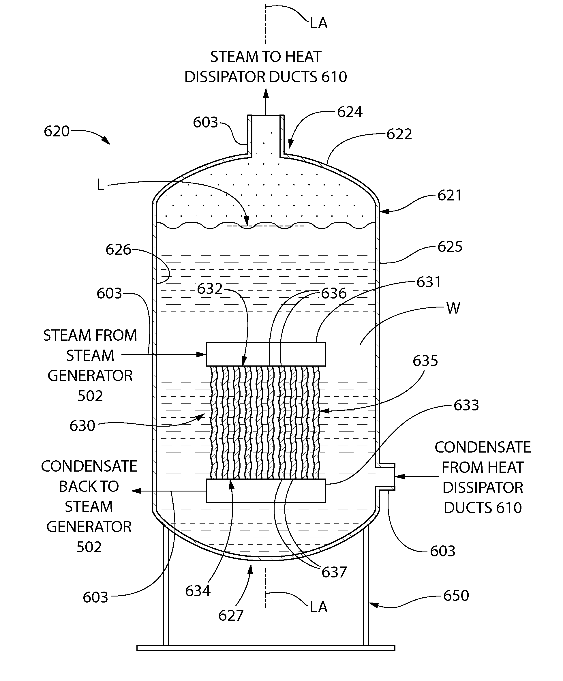
A nuclear reactor cooling system with passive cooling capabilities operable during a reactor shutdown event without available electric power. In one embodiment, the system includes a reactor vessel with nuclear fuel core and a steam generator fluidly coupled thereto. Primary coolant circulates in a flow loop between the reactor vessel and steam generator to heat secondary coolant in the steam generator producing steam. The steam flows to a heat exchanger containing an inventory of cooling water in which a submerged tube bundle is immersed. The steam is condensed in the heat exchanger and returned to the steam generator forming a closed flow loop in which the secondary coolant flow is driven by natural gravity via changes in density from the heating and cooling cycles. In other embodiments, the cooling system is configured to extract and cool the primary coolant directly using the submerged tube bundle heat exchanger.

Description

CROSS-REFERENCE TO RELATED PATENT APPLICATIONS[0001]The present application claims the benefit of U.S. Provisional Patent Application No. 61 / 827,943 filed May 28, 2013, and is a continuation-in-part of International Patent Application No. PCT / US13 / 42070 filed May 21, 2013, which claims of benefit of U.S. Provisional Patent Application No. 61 / 649,593 filed May 21, 2012, the entireties of which are incorporated herein by reference.FIELD OF THE INVENTION[0002]The present invention relates nuclear reactors, and more particularly to a reactor and reactor containment system with passive reactor cooling system for reactor shutdown operation.BACKGROUND OF THE INVENTION[0003]The containment for a nuclear reactor is defined as the enclosure that provides environmental isolation to the nuclear steam supply system (NSSS) of the plant in which nuclear fission is harnessed to produce pressurized steam. A commercial nuclear reactor is required to be enclosed in a pressure retaining structure which...

Claims


Application Information

Patent Timeline
IPC IPC(8): G21C15/18
CPCG21C15/18G21C9/004G21C13/02G21C15/12G21D1/00G21D1/006Y02E30/00Y02E30/30
Inventor SINGH, KRISHNA P.RAJKUMAR, JOSEPH
Owner SMR INVENTEC
Why Eureka
Try Eureka