Hybrid-integrated photonic chip package with an interposer

a photonic chip and interposer technology, applied in the field of hybrid integrated chip packages, can solve the problems of high bandwidth, low power, reliability and low cost, and the inability of existing interconnection technologies to provide suitable communication characteristics, and achieve the bandwidth, size, power requirements of input/output (i/o) interfaces, and the difficulty of scaling these photonic components to meet the bandwidth, power requirements, and power requirements of future chips

Active Publication Date: 2014-10-30
ORACLE INT CORP
View PDF6 Cites 47 Cited by
  • Summary
  • Abstract
  • Description
  • Claims
  • Application Information

AI Technical Summary

Benefits of technology

[0014]Moreover, the chip package may include an input / output (I / O) integrated circuit, between the integrated circuit and the optical integrated circuit, which contains high-speed I / O circuits as well as Energy-efficient driver and receiver circuits to communicate with optical devices on the optical integrated circuit. It may also serialize / deserialize data. This I / O integrated circuit may communicate with the integrated circuit and the optical integrated circuit via the interposer.

Problems solved by technology

As integrated-circuit (IC) technology continues to scale to smaller critical dimensions, it is increasingly difficult for existing interconnection technologies to provide suitable communication characteristics, such as: high bandwidth, low power, reliability and low cost.
However, while photonic technologies based on vertical cavity surface-emitting lasers (VCSELs) and optical fibers are typically a convenient and cost-effective solution to communicate modest amounts of data in certain parts of systems (such as between racks and, in certain cases, between boards within a rack), it is often difficult to scale these photonic components to meet the bandwidth, size, and power requirements of input / output (I / O) interfaces for future chips.
However, it can be difficult to integrate optical integrated circuits with conventional integrated circuits in existing chip packages.

Method used


Image

  • Hybrid-integrated photonic chip package with an interposer
  • Hybrid-integrated photonic chip package with an interposer
  • Hybrid-integrated photonic chip package with an interposer

Examples


Embodiment Construction

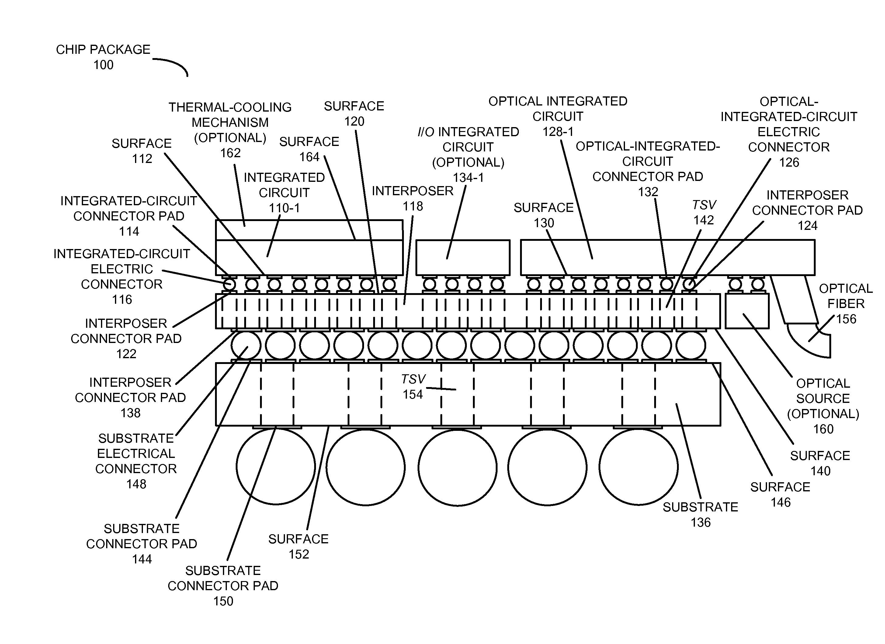
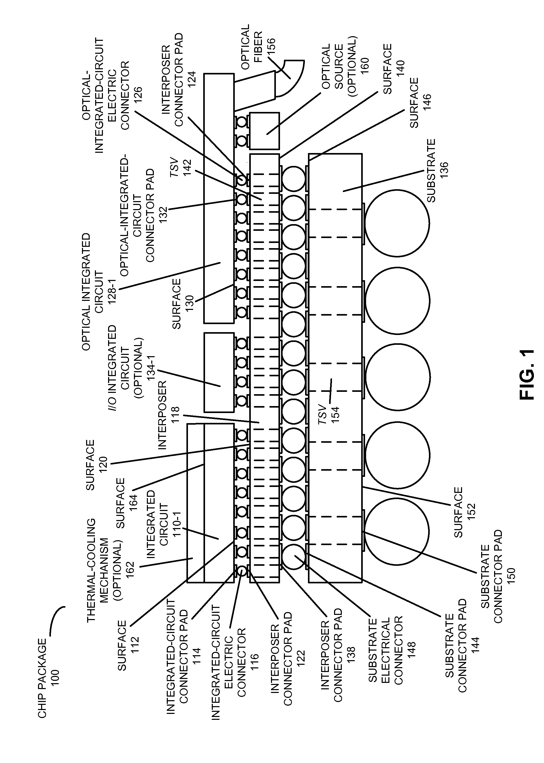
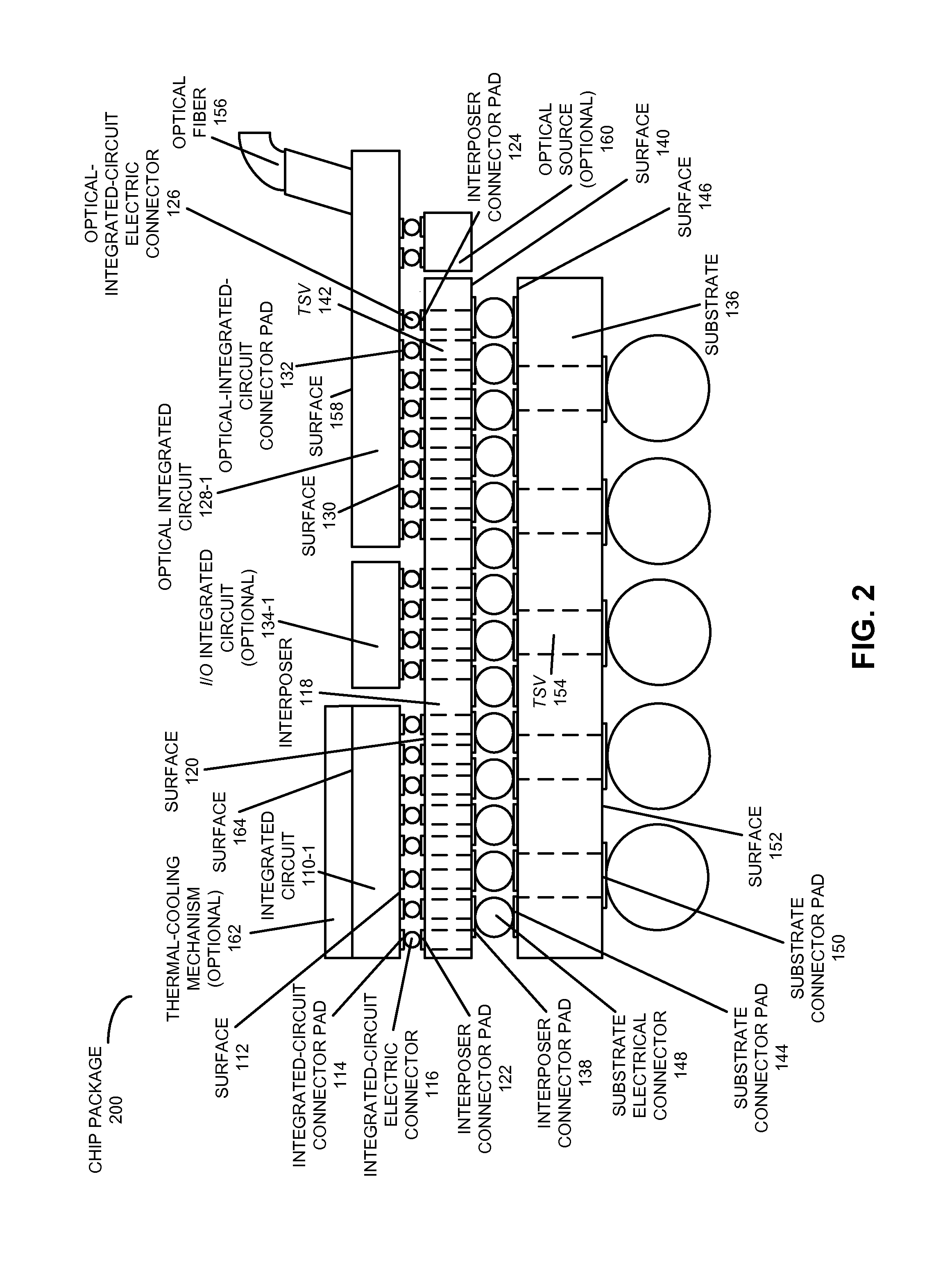
[0042]Embodiments of a chip package, a system that includes the chip package, and a technique for communicating electrical signals between an integrated circuit and an optical integrated circuit in the chip package are described. This chip package includes an optical integrated circuit (such as a hybrid integrated circuit) and an integrated circuit that are adjacent to each in the chip package. The integrated circuit includes electrical circuits, such as memory or a processor, and the optical integrated circuit communicates optical signals with very high bandwidth. Moreover, a front surface of the integrated circuit is electrically coupled to a front surface of the optical integrated circuit by a top surface of the interposer, where the top surface faces the front surface of the integrated circuit and the front surface of the optical integrated circuit. Furthermore, the integrated circuit and the optical integrated circuit may be on a same side of the interposer.

[0043]By integrating...


PUM


Abstract

A chip package includes an optical integrated circuit (such as a hybrid integrated circuit) and an integrated circuit that are adjacent to each in the chip package. The integrated circuit includes electrical circuits, such as memory or a processor, and the optical integrated circuit communicates optical signals with very high bandwidth. Moreover, a front surface of the integrated circuit is electrically coupled to a front surface of the optical integrated circuit by a top surface of the interposer, where the top surface faces the front surface of the integrated circuit and the front surface of the optical integrated circuit. Furthermore, the integrated circuit and the optical integrated circuit may be on a same side of the interposer. By integrating the optical integrated circuit and the integrated circuit in close proximity, the chip package may facilitate improved performance compared to chip packages with electrical interconnects.

Description

CROSS-REFERENCE TO RELATED APPLICATIONS[0001]This application claims priority under 35 U.S.C. §119(e) to U.S. Provisional Application Ser. No. 61 / 816,420, entitled “Multi Terabit-Per-Second Wavelength-Division-Multiplexed Photonic I / O Package,” by Hiren D. Thacker, Frankie Y. Liu, Robert D. Hopkins, Jon Lexau, Xuezhe Zheng, Guoliang Li, Ivan Shubin, Ronald Ho, John E. Cunningham, and Ashok V. Krishnamoorthy, Attorney Docket Number ORA13-0836-PSP, filed on Apr. 26, 2013, the contents of which is herein incorporated by reference.[0002]This application is related to U.S. Non-provisional patent application Ser. No. ______, entitled “Hybrid-Integrated Photonic Chip Package with an Interposer,” by Hiren D. Thacker, Ashok V. Krishnamoorthy, Robert D. Hopkins, Jon Lexau, Xuezhe Zheng, Ronald Ho, Ivan Shubin, and John E. Cunningham, Attorney Docket Number ORA14-0235CIP, filed on ______, 2013; and to U.S. Non-provisional patent application Ser. No. ______, entitled “Hybrid-Integrated Photonic...

Claims


Application Information

Patent Timeline
Patent Type & Authority Applications(United States)
IPC IPC(8): G02B6/12
CPCG02B6/12004G02B6/4274H01L24/13H01L24/14H01L24/16H01L24/32H01L24/72H01L24/73H01L24/81H01L24/92H01L25/0652H01L25/0655H01L2224/0401H01L2224/13147H01L2224/1403H01L2224/16145H01L2224/16225H01L2224/32225H01L2224/72H01L2224/73204H01L2224/73253H01L2224/81203H01L2224/81815H01L2224/92125H01L2225/06513H01L2225/06517H01L2225/06534H01L2225/06589H01L2924/14H01L2924/15192H01L2924/15311H01L2924/157H01L2924/15787H01L2924/15788H01L2924/37001H05K3/36H05K2201/10484H01L2924/00
Inventor THACKER, HIREN D.LIU, FRANKIE Y.HOPKINS, II, ROBERT DAVIDLEXAU, JONZHENG, XUEZHELI, GUOLIANGSHUBIN, IVANHO, RONALDCUNNINGHAM, JOHN E.KRISHNAMOORTHY, ASHOK V.
Owner ORACLE INT CORP
Why Eureka
Try Eureka