Rotary table device
a technology of rotary table and rotary plate, which is applied in the direction of manufacturing tools, mechanical equipment, metal-working machine components, etc., can solve the problems of deteriorating resin materials, electrical hazards, and affecting the insulation properties of electric components, and achieve the effect of preventing the penetration of cutting fluid
- Summary
- Abstract
- Description
- Claims
- Application Information
AI Technical Summary
Benefits of technology
Problems solved by technology
Method used
Image

Examples
first embodiment
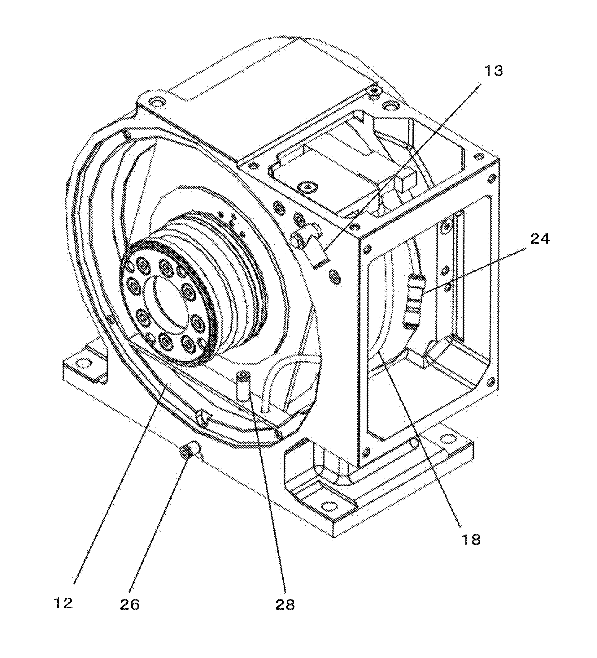
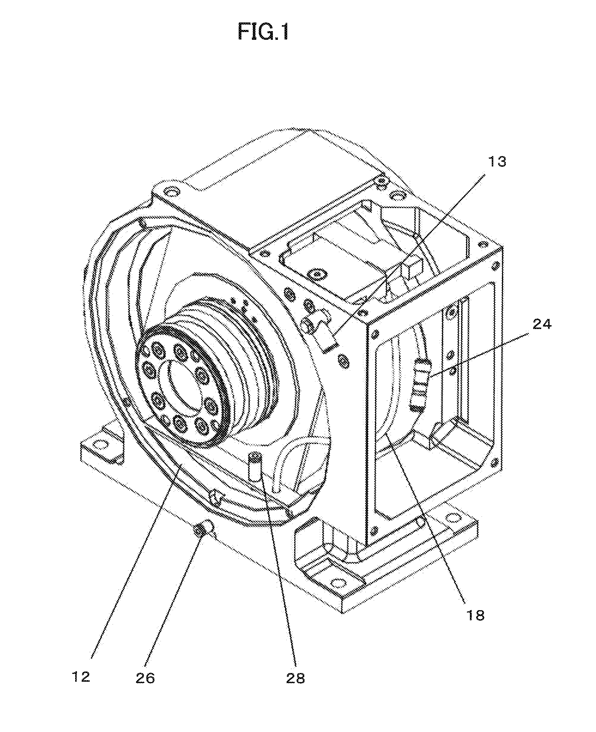
[0028]First of all, the rotary table device according to the present invention is described with reference to FIGS. 1 to 3.
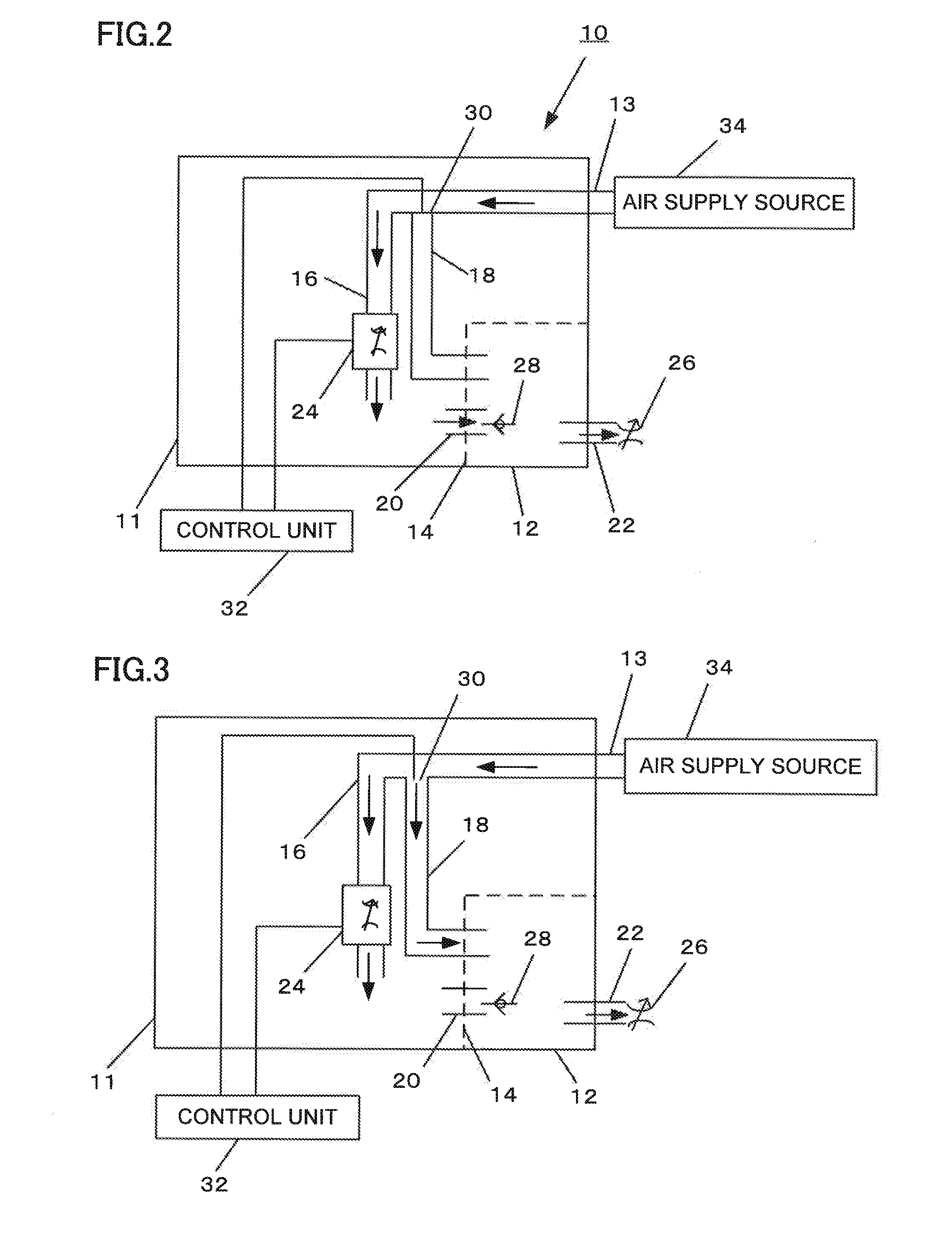
[0029]As shown in FIG. 2, the inside of a case 10 is divided into a first room 11 and a second room 12 by a partitioning member 14. The partitioning member 14 is provided with an inter-room air supply path 20. The inter-room air supply path 20 is provided with a check valve 28.
[0030]An air supply source 34 is connected to an air supply port 13 of the case 10 so that air is supplied from the air supply source 34 into the case through the air supply port 13. The air supplied through the air supply port 13 is then supplied to a first air supply path 16 and then to the first room 11 through a first regulating valve 24. An air branch point 30 is provided in the middle of the first air supply path 16, in which a second air supply path 18 branches off from the air branch point 30.
[0031]As will be described below, the air branch point 30 is configured to be able to open...
second embodiment
[0043]Next, the rotary table device according to the present invention is described with reference to FIG. 4.
[0044]The difference between the second embodiment and the first embodiment is that the second air supply path 18 is provided with a second regulating valve 25. As with the first regulating valve 24, the second regulating valve 25 functions to lower the pressure of the air supplied from the air supply source 34 and is capable of changing the rate of pressure decline by means of the control unit 32 connected to the first regulating valve 24 and the second regulating valve 25.
[0045]In this embodiment as well, regulation by the control unit 32 can normally make the pressure of the first room 11 higher than the pressure of the second room 12, and reverse the relationship between the pressure of the first room 11 and the pressure of the second room 12 every certain time period, to make the pressure of the second room 12 higher than the pressure of the first room 11. Such a configu...
third embodiment
[0046]the rotary table device according to the present invention is described next with reference to FIG. 5.
[0047]The differences between the third embodiment and the second embodiment are that an air supply source (first air supply source 36) is connected to the air supply port 13 connected to the first air supply path 16, and that an air supply source (second air supply source 38) is connected to an air supply port (second air supply port 15) connected to the second air supply path 18.
[0048]The pressure within the first room 11 and the pressure within the second room 12 are regulated by means of the first regulating valve 24 and the second regulating valve 25 as with the second embodiment but can also be regulated by regulating the outputs of the first air supply source 36 and the second air supply source 38, or the regulation can be also implemented by regulating both the first and second regulating valves as well as outputs of the air supply sources simultaneously.
PUM
 Abstract
Description
Claims
Application Information
 - R&D
- Intellectual Property
- Life Sciences
- Materials
- Tech Scout
- Unparalleled Data Quality
- Higher Quality Content
- 60% Fewer Hallucinations
Browse by: Latest US Patents, China's latest patents, Technical Efficacy Thesaurus, Application Domain, Technology Topic, Popular Technical Reports.
© 2025 PatSnap. All rights reserved.Legal|Privacy policy|Modern Slavery Act Transparency Statement|Sitemap|About US| Contact US: help@patsnap.com