Weather radar

a weather radar and radar technology, applied in the field of weather radars, can solve the problems of inability to determine the absolute value of calibration parameters, such as amplification or noise, and the inability to accurately determine the calibration parameters of individual signal paths, and achieve the improvement of the comparability of the measured data in the tx sample channel and the other receiver channels over time, and the accuracy of determining calibration parameters

Active Publication Date: 2014-11-06
LEONARDO GERMANY GMBH
View PDF2 Cites 16 Cited by
  • Summary
  • Abstract
  • Description
  • Claims
  • Application Information

AI Technical Summary

Benefits of technology

[0008]The object of the invention is therefore to improve the measurement of the signal strength in weather radars.

Problems solved by technology

A disadvantage of this calibration method is that the data recording of the weather radar must be interrupted during the calibration or range cells must be blocked and excluded from the operational useful signal processing.
This weather radar also has the disadvantage that the data recording must be interrupted during the calibration or range cells must be blocked and excluded from the operational useful signal processing.
This calibration method has the disadvantage that the two signal paths can only be calibrated relative to one another, so that absolute values for calibration parameters, such as amplification or noise, of the individual signal paths and their time dependence cannot be determined.

Method used


Image

  • Weather radar
  • Weather radar
  • Weather radar

Examples


Embodiment Construction

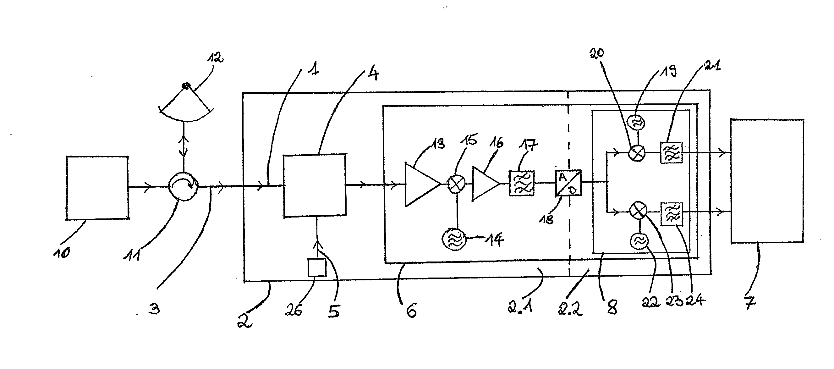
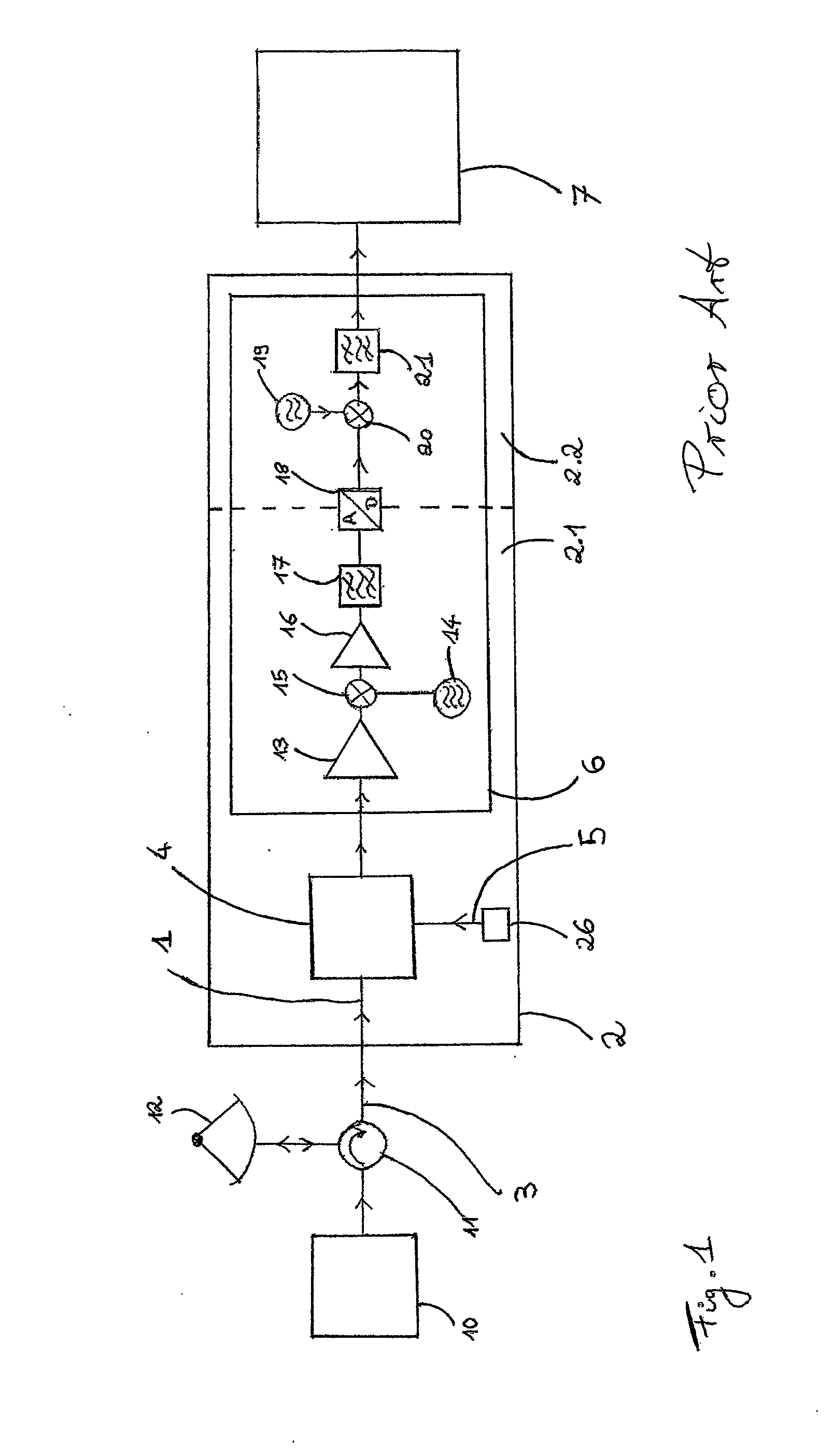
[0030]FIG. 1 shows a block diagram of a weather radar according to the prior art. A radar pulse generated by a transmitter 10 can be fed in a transmission interval via a duplexer 11 to an antenna 12. In the subsequent receiving phase, the backscattered radar signal 3 received from the antenna 12 can be fed by the duplexer 11 to the receiving facility of the weather radar receiver 2.

[0031]In the signal path 1 within the receiver 2, a test signal 5 generated by a test signal generator 26 can be superimposed on the radar signal 3 via a coupler 4. According to the prior art, the frequency of the test signal 5 corresponds to that of the radar signal 3. The two superimposed signals 3, 5 can then be fed to the processing device 6 to amplify, filter and convert the two signals 3, 5.

[0032]Customary processing steps within the processing device 6 are a pre-amplification of the GHz signal by a low-noise amplifier 13, the conversion of the high-frequency signal into an intermediate frequency in...


PUM


Abstract

Weather radar for measuring radar signals in the GHz range with a receiver containing at least one signal path, the receiver comprising a receiving facility for an incoming radar signal, on which a test signal generated by a test signal generator is superimposed in a coupler, and a processing device to amplify, filter and convert both signals to lower frequencies, wherein for filtering a matched filter is provided, and with an evaluation device in which calibration parameters of the signal path are derived from the test signal for the frequency of the test signal in order to determine the signal strength of the received radar signal, wherein the test signal is superimposed with at least one frequency differing from the frequency of the radar signal, so that the radar signal and the test signal are processed separately from one another by the evaluation device, and the calibration parameters of the signal path for the frequency of the radar signal are determinable from the test signal through a modeling of the frequency dependence of the calibration parameters for frequencies around those of the radar signal.

Description

BACKGROUND OF THE INVENTION[0001]The invention relates to a weather radar for measuring radar signals in the GHz range.[0002]Weather radars transmit high-power microwave pulses and measure the strength of the signal that is backscattered by rain or other targets. The rain quantity, for example, can then be estimated from the signal strength. A calibration of the weather radar and, in particular, its receiver is required for this purpose.[0003]From WO 2011 / 001206 A1 a multichannel receiver system is known allowing for automatic gain calibration by relating the amplitude of a reference signal before coupling it into a receiving path and the amplitude of the reference signal comprised in an output signal of the receiving path and eliminating or reducing changes in conversion gain.[0004]DE 10 2011 012 843 A1 relates to a driver assistance device for a vehicle having a radar unit for detecting a measured variable which determines a frequency-dependent correction quantity for correcting t...

Claims


Application Information

Patent Timeline
Patent Type & Authority Applications(United States)
IPC IPC(8): G01S13/95
CPCG01S13/95G01S7/4021G01S7/4052G01S13/951G01S7/4069Y02A90/10
Inventor BEYER, STEFAN
Owner LEONARDO GERMANY GMBH
Why Eureka
Try Eureka