
Lead-Carbon Battery Current Collector Shielding with Ported Packets

Active Publication Date: 2014-11-06
WAINWRIGHT D WALKER
View PDF0 Cites 11 Cited by
  • Summary
  • Abstract
  • Description
  • Claims
  • Application Information

AI Technical Summary

Benefits of technology

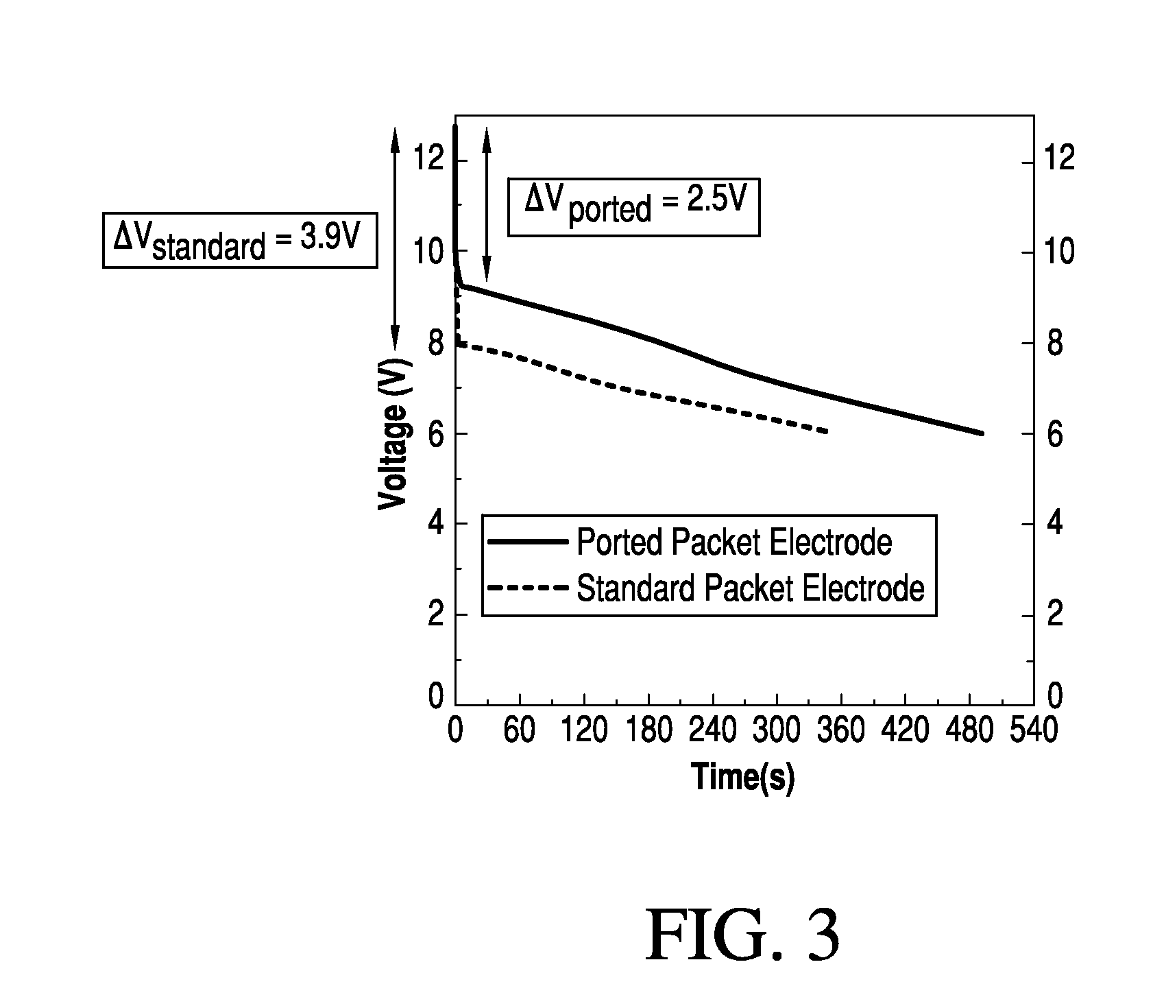
This patent describes a method for improving the performance of a negative electrode in an energy storage device. The method includes steps to reduce the resistance between the electrodes and improve the uniformity of the battery performance. This is achieved by a method involving the removal of a portion of the copper current collector and the creation of a port hole in the graphite foil shield. This helps to reduce the contact resistance between the electrodes and also allows for the penetration of electrolyte into the space between the current collector and graphite shield, resulting in improved battery performance. The invention also addresses the issue of cell compression variability caused by trapped air and reduces the resistance over time.

Problems solved by technology

Manufacture of low resistance standard packets with a leak-free expanded graphite foil negative electrode structure has proven challenging.
Efforts were then dedicated to minimize the quantity of entrapped air accumulated during lamination but met without success.
However, the entrapped air could not be eliminated.
Furthermore, in addition to the undesirable increased packet resistance, the variable amount of entrapped air also caused manufacturing difficulties in respect to the force required to compress the cell to the size of the case opening.
Because entrapped air acts like a spring during compression, if the entrapped air volume is too large it causes glue line failure during compression leading to the escape of air from and electrolyte penetration into the packet.
The resulting batteries made from these packets exhibited a wide resistance variation and concomitantly non-uniform performance.

Method used


Image

  • Lead-Carbon Battery Current Collector Shielding with Ported Packets
  • Lead-Carbon Battery Current Collector Shielding with Ported Packets
  • Lead-Carbon Battery Current Collector Shielding with Ported Packets

Examples


Embodiment Construction

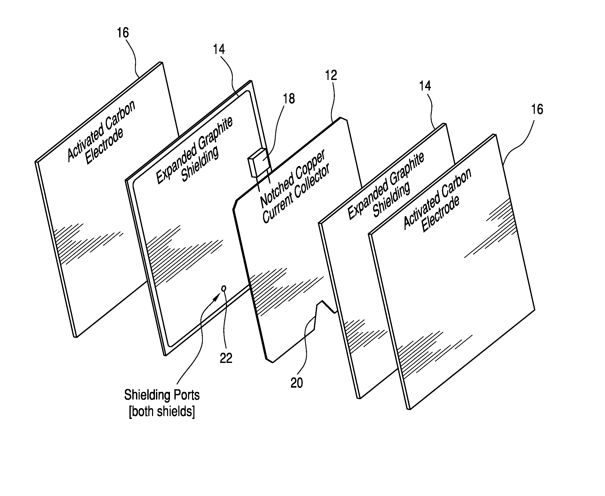
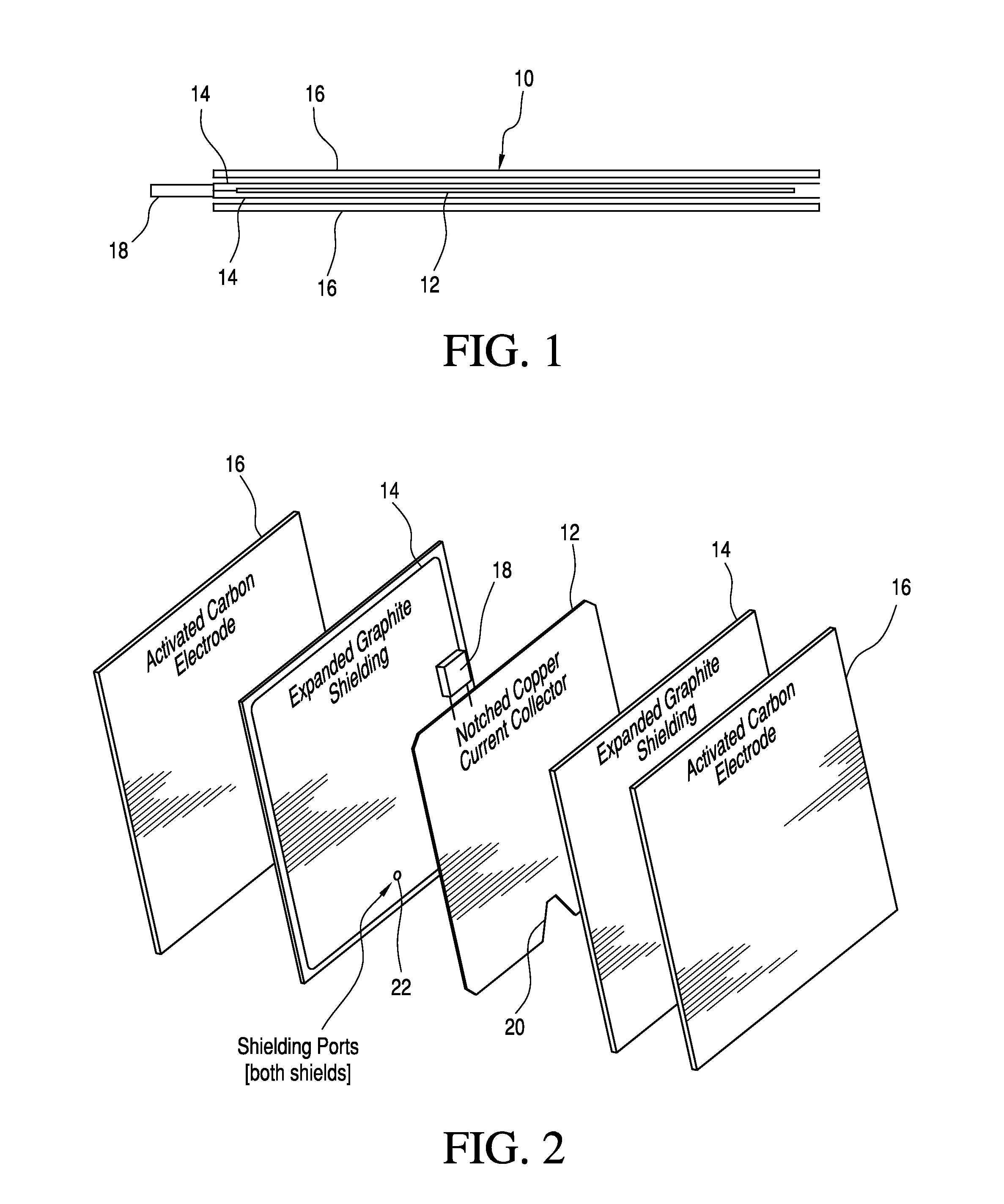
[0027]FIGS. 1 and 2 depict a carbon negative electrode 10 constructed according to the ported packet version of the invention. A central copper metal current collector 12 is encased in two layers of expanded graphite shieling 14 which are each covered by activated carbon sheet 16. A collector tab 18 projects from the top edge of the current collector 12 and the bottom edge of collector 12 features a notch 20 preferably of a generally triangular geometry although not limited to such, is disposed at a location to achieve maximal separation from the tab 18. The notch 20 is covered on both sides by the expanded graphite shield (gasket) 14, which preferably is paraffin impregnated and preferably exhibits high conductivity, corrosion resistance, and stability from 0.7 V (SHE) to 1.0 V (SHE).

[0028]Each side of the graphite sheet shield 14 includes a small diameter circular hole / port 22 extending through its thickness. Given the potential for copper oxidation of the copper current collector...


PUM

PropertyMeasurementUnit
Fractionaaaaaaaaaa
Diameteraaaaaaaaaa
Diameteraaaaaaaaaa

Abstract

Provided is an activated carbon lead energy storage / battery containing an improved negative activated electrode packet exhibiting substantially reduced resistance with ported paraffin impregnated expanded graphite foil shielding overlying a cutaway notch in the underlying current collector to permit sulfuric acid electrolyte infiltration.

Description

PRIORITY CLAIM[0001]This application claims the benefit of U.S. Provisional Application Ser. No. 61 / 818,727 filed on May 2, 2013 which is incorporated herein by reference.FIELD OF INVENTION[0002]This invention relates to a modification improving a lead-carbon battery current collector for an activated carbon electrode. More particularly, the improvement includes the combination of a copper plate current collector with at least one notch formed in the edge opposite of that of the collector's projecting tab and a pair of ports, one each respectively, formed in the sandwiching expanded graphite shields which are located to substantially overlie the centroid of the underlying notch. The counterintuitive modification contemplated by the invention herein, while simple, facilitates and improves the electrode / battery resistance and increases battery power performance and is particularly suited for use in connection with existing activated carbon lead negative electrode (and thus battery / ene...

Claims


Application Information

Patent Timeline
IPC IPC(8): H01M4/70H01M4/04
CPCH01M4/70H01M2004/027H01M4/04H01M4/68H01M4/82H01M10/06H01M2004/021Y02E60/10Y10T29/49108
Inventor DICKINSON, ENDERSSHINDLE, JACK A.
Owner WAINWRIGHT D WALKER
Learn More