Direct injection of diluents or secondary fuels in gaseous fuel engines

a gaseous fuel engine and diluent technology, applied in the direction of machines/engines, mechanical equipment, non-fuel substance addition to fuel, etc., can solve the problems of increasing the likelihood of engine knock, numerous operating problems, and the temperature limit of the engine may be reached prior to the conversion to cng, so as to reduce the exhaust emissions and reduce the price of conventional fuels.

Inactive Publication Date: 2014-11-13
FORD GLOBAL TECH LLC
View PDF12 Cites 26 Cited by
  • Summary
  • Abstract
  • Description
  • Claims
  • Application Information

AI Technical Summary

Benefits of technology

[0001]Alternate fuels have been developed to mitigate the rising prices of conventional fuels and for reducing exhaust emissions. For example, natural gas has been recognized as an attractive alternative fuel. For automotive applications, natural gas may be compressed and stored as a gas in cylinders at high pressure. Various engine systems may be used with CNG fuels, utilizing various engine technologies and injection technologies that are adapted to the specific physical and chemical properties of CNG fuels. For example, mono-fuel engine systems may be configured to operate with CNG while multi-fuel systems may be configured to operate with CNG and one or more other fuels, such as gasoline or gasoline blend liquid fuels. Engine control systems may operate such multi-fuels systems in various operating modes based on engine operating conditions.

Problems solved by technology

However, CNG engines, particularly engines that have been converted to run on CNG, may experience numerous operating problems.
Thus, when running a CNG engine at high loads, the temperature limit of the engine may be reached prior to fully combusting the fuel or air taken into the combustion cylinder.
By not fully combusting the contents of the combustion cylinder, the likelihood of engine knock increases.
This reduces the natural lubrication of engine valves, potentially leading to valve recession and degradation.
To counter overheating problems, the air charge may be limited by either throttling airflow or running lean, but these solutions may limit the maximum power output of the engine.
Specific power may be increased by increasing the size of the engine, but this may not be possible for all platforms or conversions.
Injecting water or other control fluids into the combustion chamber may reduce temperatures and guard against engine knock, but may further reduce the ignitability of the fuel mixture.
CNG engines also experience increased valve wear for a number of reasons.

Method used


Image

  • Direct injection of diluents or secondary fuels in gaseous fuel engines
  • Direct injection of diluents or secondary fuels in gaseous fuel engines
  • Direct injection of diluents or secondary fuels in gaseous fuel engines

Examples


Embodiment Construction

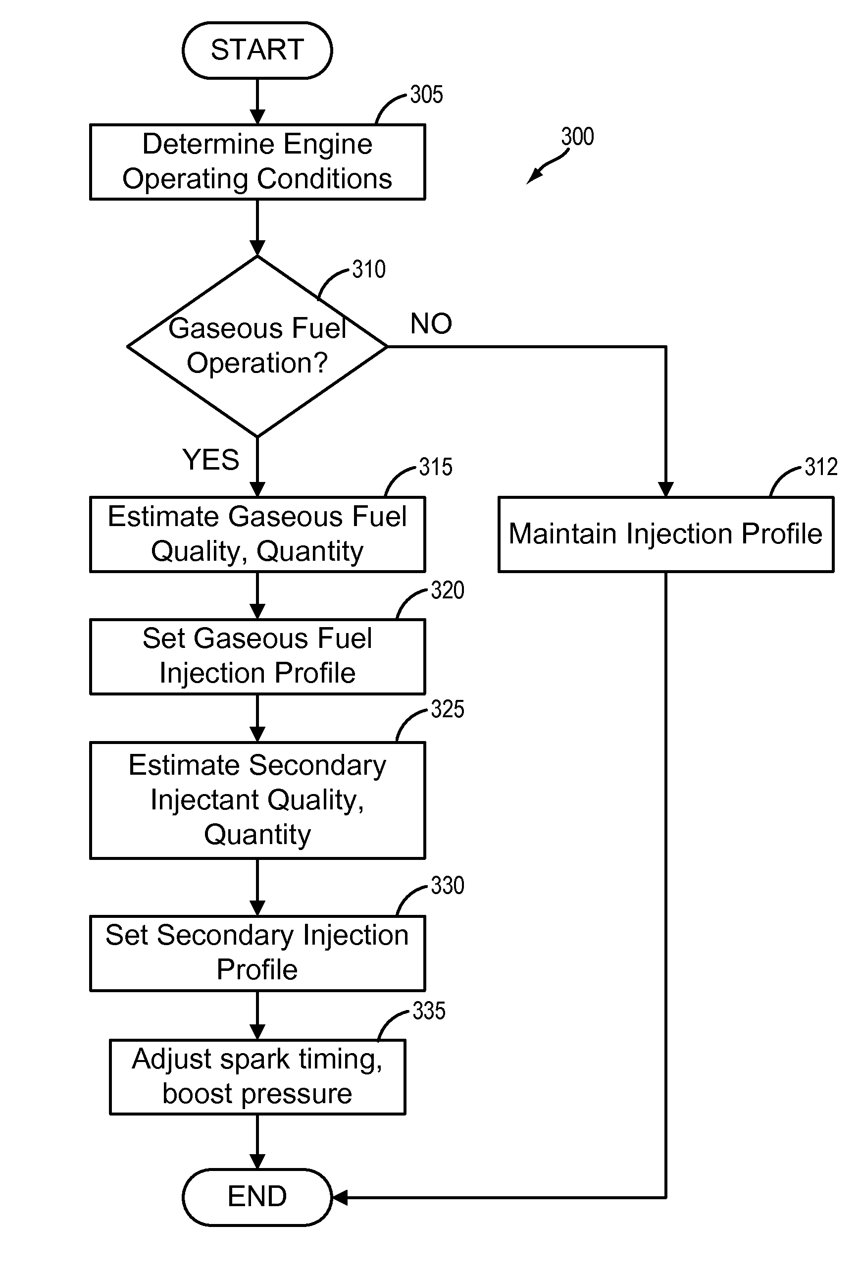
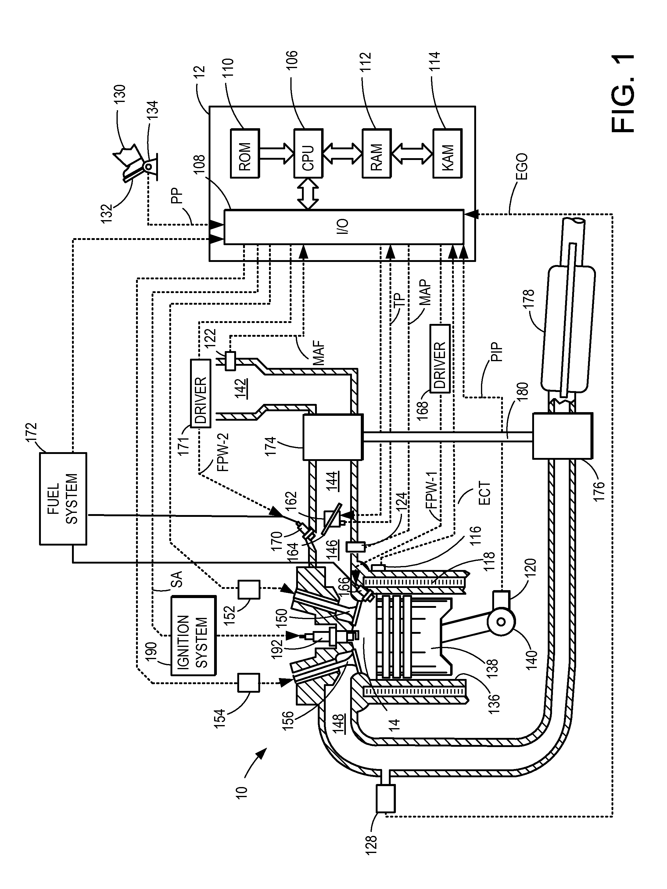
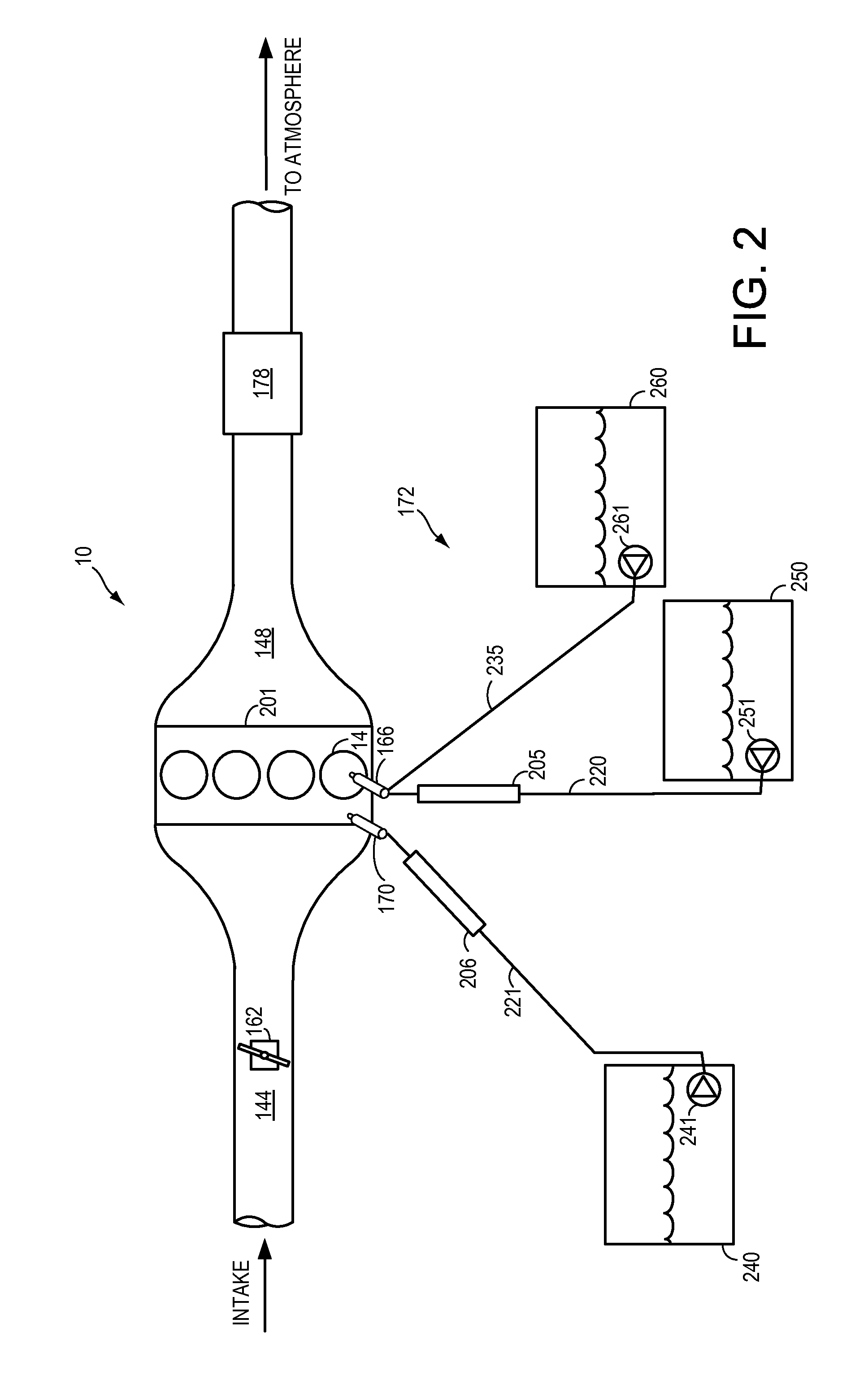
[0024]The following description relates to systems and methods for addressing overheating and engine knock in gaseous fueled engines, such as the engines schematically diagrammed in FIGS. 1 and 2. The systems may include a gaseous fuel tank coupled to a port-fuel injector and a secondary fuel tank of reservoir coupled to a direct-fuel injector. A controller may be programmed to control the rate and timing of fuel injection through a control routine, such as the routines described in FIGS. 3, 4, 6 and 8. The timing of fuel injection may be set to coincide with events during the combustion cycle of an engine cylinder, as depicted in FIGS. 5 and 7. An example embodiment of an engine system with an EGR and reformer device is shown in FIG. 10. The reformer device may be used in accordance to this disclosure to provide a secondary gaseous fuel source. A control routine for a system such as that depicted in FIG. 10 is shown in FIG. 11. Further, the direct-fuel injection may be controlled t...


PUM


Abstract

An engine system, comprising a first gaseous fuel source with a first gaseous fuel located therein coupled to one or more engine cylinders and an exhaust gas recirculation (EGR) system with a reform catalyst located therein, the reform catalyst reforming natural gas into a gas with a wider AFR operating range. The engine may thus operate at an AFR that may be outside of that available during natural gas combustion alone to allow for cooler engine operation.

Description

BACKGROUND AND SUMMARY[0001]Alternate fuels have been developed to mitigate the rising prices of conventional fuels and for reducing exhaust emissions. For example, natural gas has been recognized as an attractive alternative fuel. For automotive applications, natural gas may be compressed and stored as a gas in cylinders at high pressure. Various engine systems may be used with CNG fuels, utilizing various engine technologies and injection technologies that are adapted to the specific physical and chemical properties of CNG fuels. For example, mono-fuel engine systems may be configured to operate with CNG while multi-fuel systems may be configured to operate with CNG and one or more other fuels, such as gasoline or gasoline blend liquid fuels. Engine control systems may operate such multi-fuels systems in various operating modes based on engine operating conditions.[0002]However, CNG engines, particularly engines that have been converted to run on CNG, may experience numerous opera...

Claims


Application Information

Patent Timeline
Patent Type & Authority Applications(United States)
IPC IPC(8): F02M25/07
CPCF02M25/074F02M25/0742F02D19/027Y02T10/30F02M26/36
Inventor BIDNER, DAVID KARLDEARTH, MARK ALLEN
Owner FORD GLOBAL TECH LLC
Why Eureka
Try Eureka