Mask assembly and method for fabricating the same

a mask and assembly technology, applied in the field of mask assembly and a method, can solve the problems of unit mask not being able to endure the pulling force of the clamp, wave may occur around, and the mask may not be able to effectively remove the waves, so as to achieve stable prolongation, reduce the effect of deposition quality and effective removal of waves

Active Publication Date: 2014-11-13
SAMSUNG DISPLAY CO LTD
View PDF2 Cites 26 Cited by
  • Summary
  • Abstract
  • Description
  • Claims
  • Application Information

AI Technical Summary

Benefits of technology

[0017]As the mask assembly according to an embodiment of the present invention is extended in the first direction, the plurality of unit masks, on which waves occur, are extended in the second direction to effectively remove the waves. Accordingly, deformation of the openings of the patterns of the plurality of unit masks due to the waves can be suppressed, and thus the deposition quality of the thin film can be increased.
[0018]Further, as the mask assembly according to an embodiment of the present invention fixes projections, which project in the second direction from both end portions of at least one of the plurality of unit masks, to the extension unit, the unit masks can stably maintain the extended state in the second direction even after the forming of the mask assembly is completed.

Problems solved by technology

In this case, however, contraction phenomenon may occur in a direction that is orthogonal to the extension direction, that is, in the width direction, and this may cause waves to occur on the whole mask.
Further, end portions of both sides of the unit mask are fixed to clamps and extended, and as the unit mask itself is formed of a thin metal plate material, the unit mask may not be able to endure a pulling force of the clamp, and thus waves may occur around the end portion fixed to the clamp.
The waves occurring on the end portion of the unit mask may reach even a center portion of the unit mask on which the opening is formed to cause deposition inferiority.
The waves occurring around the welding point of the unit mask are extended up to the center portion of the unit mask to cause the deposition inferiority.

Method used


Image

  • Mask assembly and method for fabricating the same
  • Mask assembly and method for fabricating the same
  • Mask assembly and method for fabricating the same

Examples


Embodiment Construction

[0034]Exemplary embodiments of the present invention may, however, be embodied in many different forms and should not be construed as being limited to exemplary embodiments set forth herein.

[0035]It will also be understood that when a layer is referred to as being “on” another layer or substrate, it can be directly on the other layer or substrate, or intervening layers may also be present. The same reference numbers indicate the same components throughout the specification.

[0036]As used herein, the term “and / or” includes any and all combinations of one or more of the associated listed items. Also, as used herein, the singular forms “a,”“an” and “the” are intended to include the plural forms as well, unless the context clearly indicates otherwise.

[0037]Hereinafter, exemplary embodiments of the present invention will be described in detail with reference to the accompanying drawings.

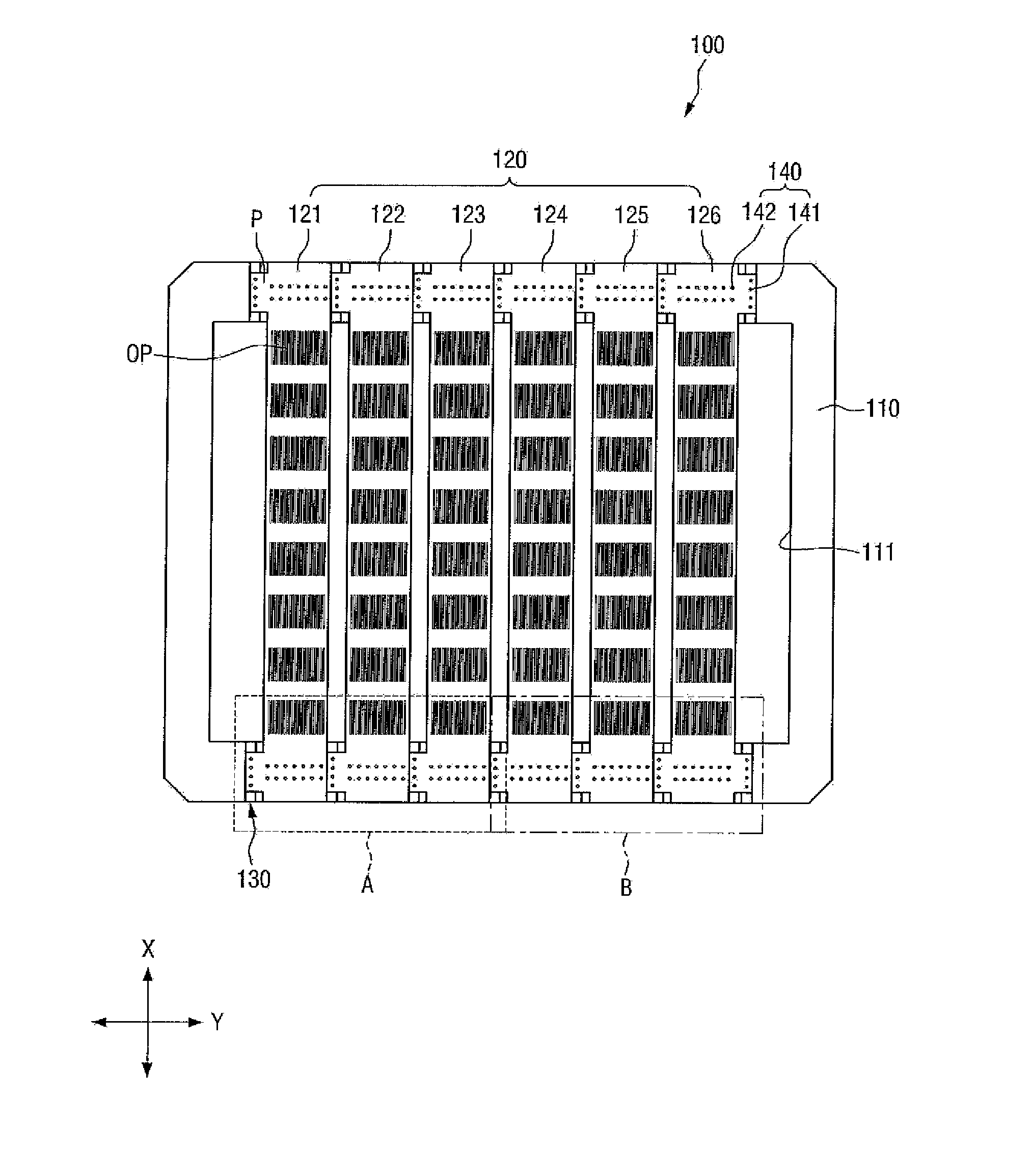
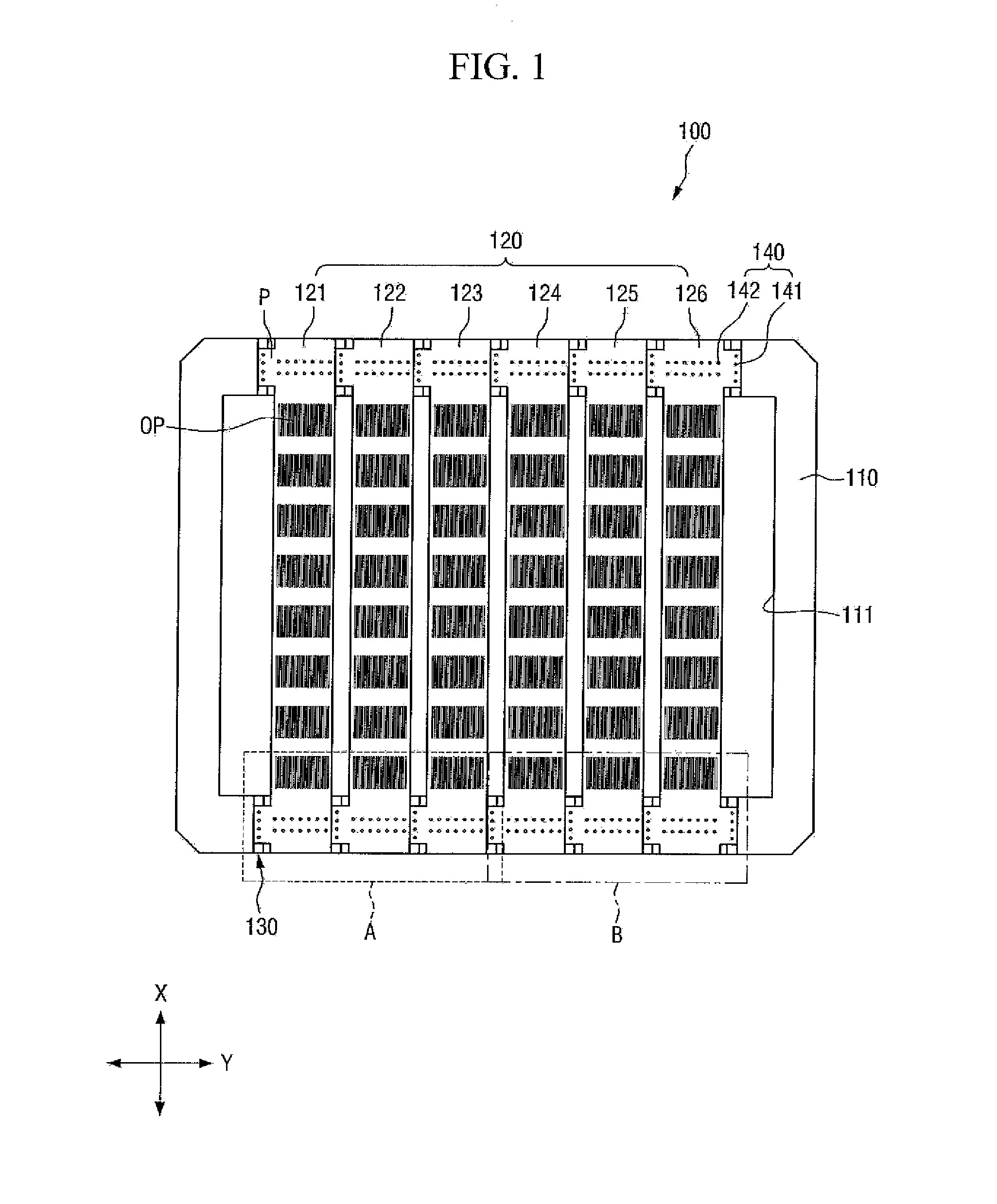
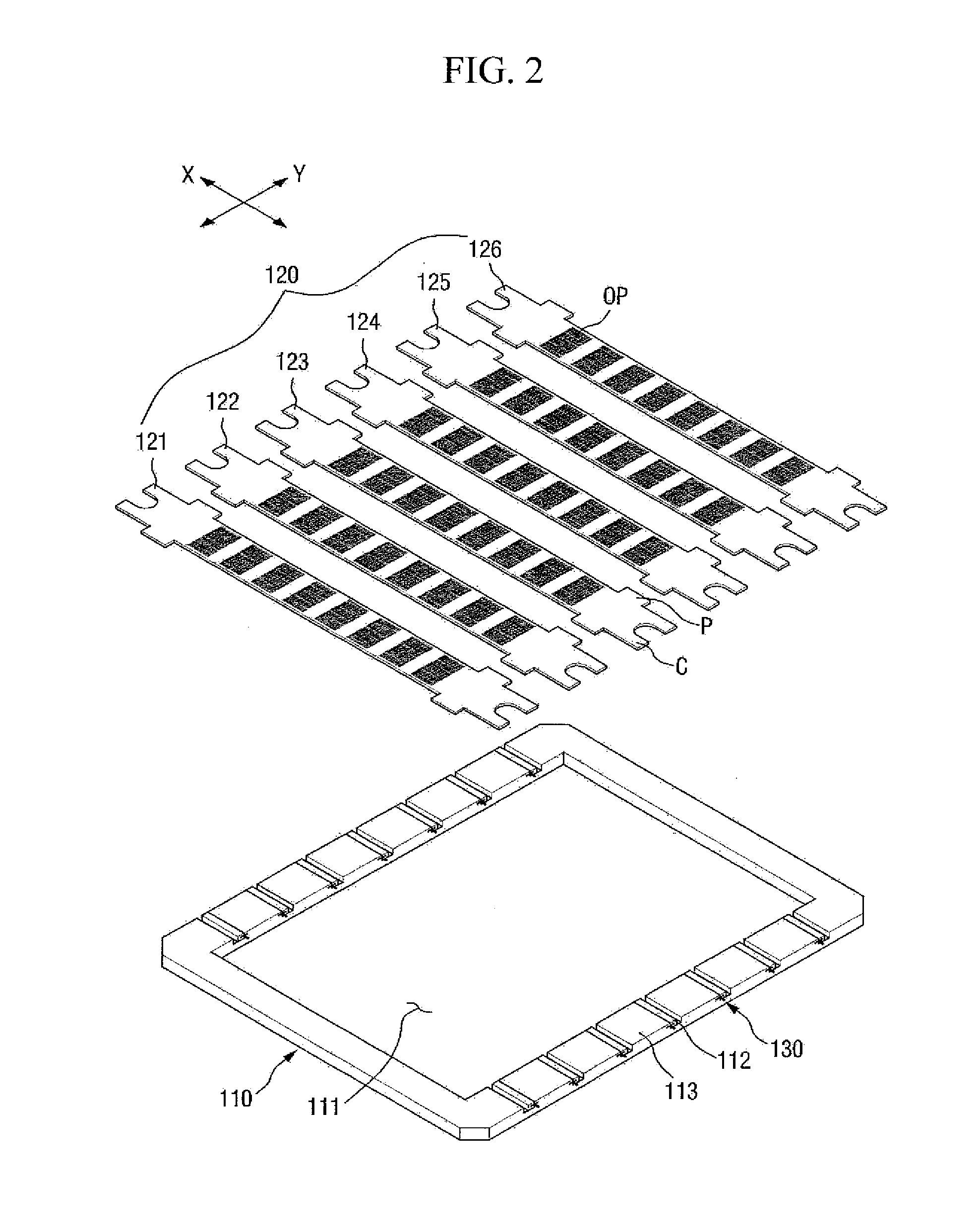
[0038]FIG. 1 is a plan view of a mask assembly according to an embodiment of the present invention, and...


PUM

PropertyMeasurementUnit
lengthaaaaaaaaaa
widthaaaaaaaaaa
pulling forceaaaaaaaaaa

Abstract

A mask assembly includes a mask frame having frame openings formed thereon, and a plurality of unit masks fixed to the mask frame. The respective unit masks extend in a first direction, and at least one of the plurality of unit masks includes at least one of a one sided projection projecting to one side thereof and another sided projection projecting to another side thereof, at both end portions of the unit mask, in a second direction that crosses the first direction.

Description

CROSS-REFERENCE TO RELATED APPLICATIONS[0001]This application is based on and claims priority from Korean Patent Application No. 10-2013-0051975, filed on May 8, 2013, the disclosure of which is hereby incorporated by reference herein in its entirety.TECHNICAL FIELD[0002]The present disclosure relates to a mask assembly and a method for fabricating the same.DISCUSSION OF THE RELATED ART[0003]As flat panel displays, a liquid crystal display (LCD) and an organic light emitting display (OLED) have been widely used. The flat panel display includes a metal layer of a specific pattern, and in the case of the organic light emitting display, an organic light emitting layer of a specific pattern is formed for each pixel. As a method for forming a metal layer and an organic light emitting layer, a deposition method using a mask assembly may be applied.[0004]The mask assembly may include a mask having openings corresponding to a pattern of a metal layer or an organic light emitting layer, and ...

Claims


Application Information

Patent Timeline
Patent Type & Authority Applications(United States)
IPC IPC(8): B05C21/00B23K37/04B23K31/02
CPCB05C21/005B23K31/02B23K37/0408C23C14/042G03F1/38G03F1/50
Inventor KIM, YONG HWAN
Owner SAMSUNG DISPLAY CO LTD
Why Eureka
Try Eureka