Bi-directional dc-dc converter

a converter and bi-directional technology, applied in the field of converters, can solve the problems of affecting the transfer efficiency of the transformer to a certain extent, increasing the current of the switching components in the bridge arms, and confined voltage spikes, so as to improve the transformer efficiency and soft-switch the switching components

Inactive Publication Date: 2014-11-13
DELTA ELECTRONICS INC
View PDF15 Cites 56 Cited by
  • Summary
  • Abstract
  • Description
  • Claims
  • Application Information

AI Technical Summary

Benefits of technology

[0006]To solve the above-mentioned problems, an object of the present disclosure is to provide a bi-directional DC-DC converter which, in part, may improve efficiency of the transformer while achieving soft switching of the switching components therein.

Problems solved by technology

There are some technical problems in the applications of a low-voltage side current-fed and high-voltage side voltage-fed isolated bi-directional DC-DC converter.
However, such switching components for achieving the soft-switching operation depend highly on the active-clamp switching components, and the active-clamp switching components per se are hard switching, which additionally increases current of switching components in the bridge arms.
Although this snubber is independent from a power circuit and the clamping voltage can be set, it is required to use leakage inductances in transformer to achieve the soft switching of the switching components in the bridge arms, which may affect transfer efficiency of the transformer to a certain extent.
Furthermore, voltage in the bridge arms may be effectively clamped by using the clamping diode in the present disclosure, and voltage spikes may be confined.

Method used


Image

  • Bi-directional dc-dc converter
  • Bi-directional dc-dc converter
  • Bi-directional dc-dc converter

Examples


embodiment 1

[0046]Hereafter, a first embodiment of the present disclosure will be described with reference to FIGS. 2-39.

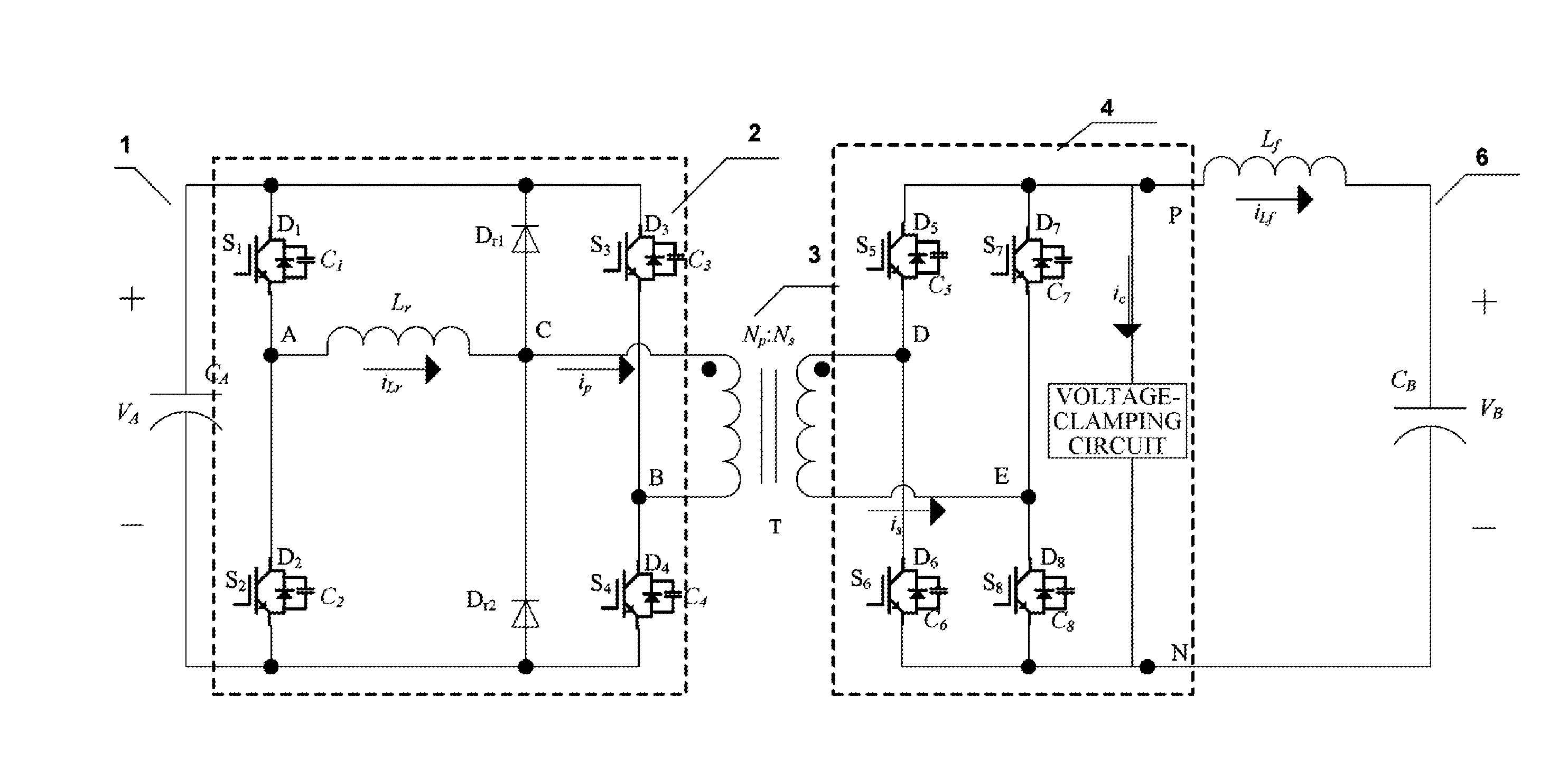
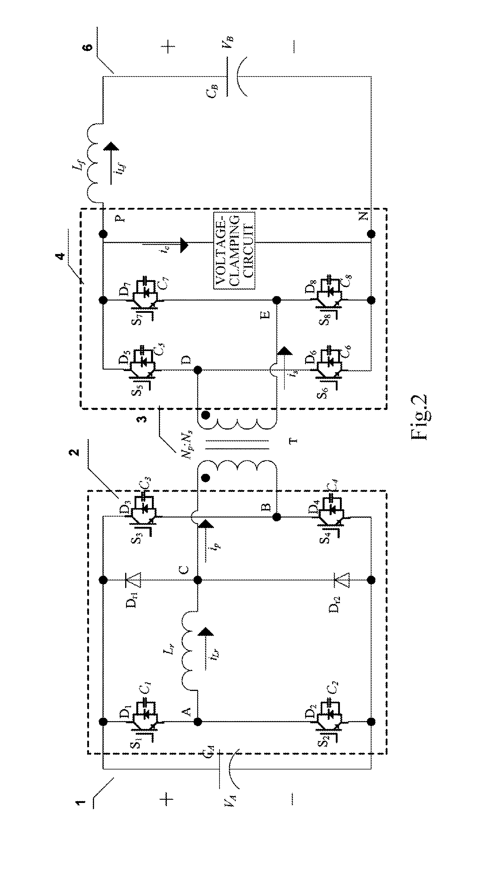
[0047]FIG. 2 shows a circuit diagram of a bi-directional DC-DC converter according to the first embodiment of the present disclosure.

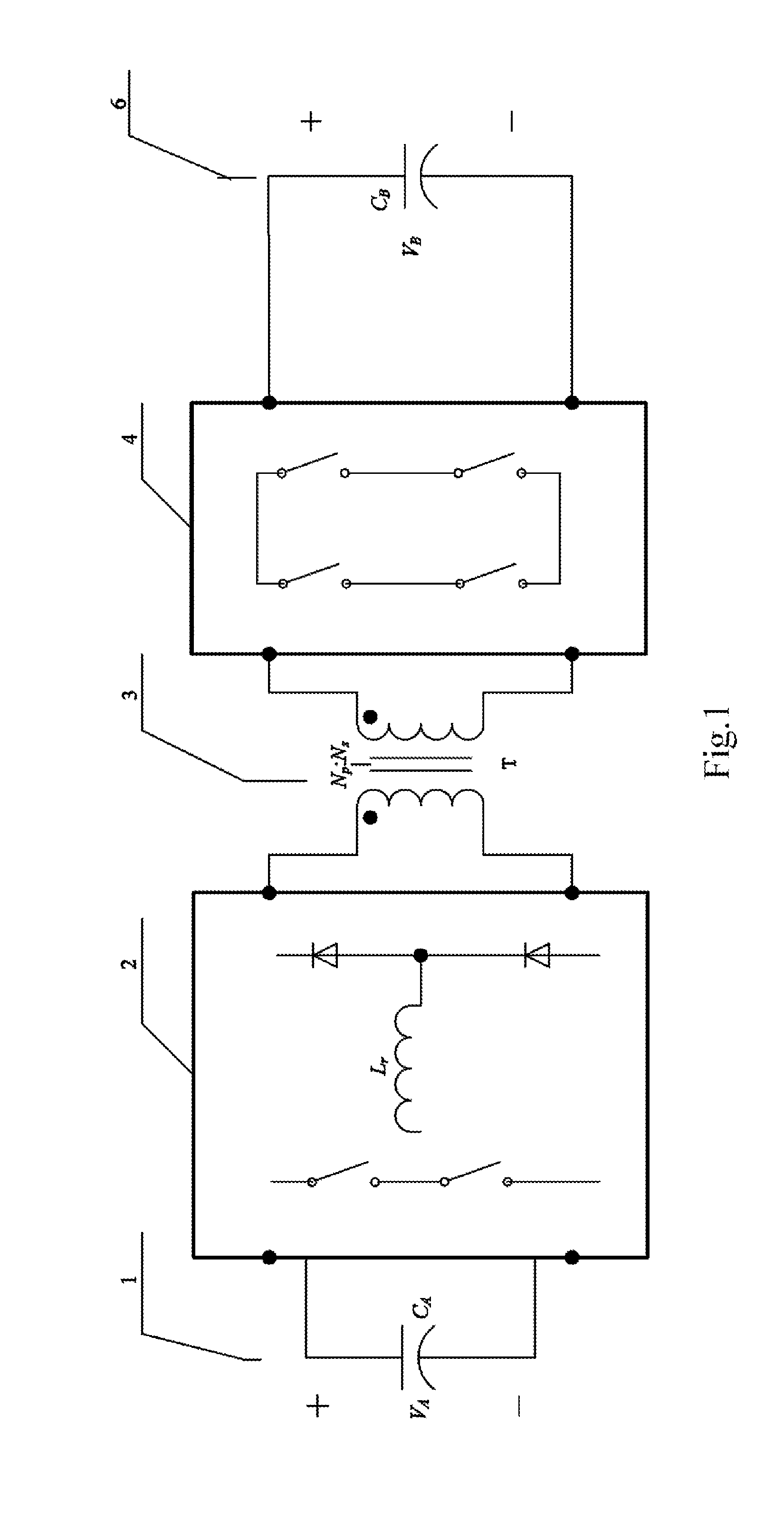
[0048]In the first embodiment of the present disclosure, the bi-directional DC-DC converter includes a primary-side DC port 1, a primary-side inverting / rectifying module 2, an isolated transformer 3, a secondary-side rectifying / inverting module 4, and a secondary-side DC port 6.

[0049]As shown in FIG. 2, the primary-side inverting / rectifying module 2 includes a first bridge arm and a clamping circuit. The first bridge arm is composed of switching components S1 and S2 connected in series, and receives a voltage VA from the primary-side DC port via a capacitor CA at high-pressure side which is connected in parallel with the first bridge arm. The clamping circuit includes a resonant inductor Lr and a clamping bridge arm composed of semiconductor dev...

embodiment 2

[0144]In the first embodiment, the operation states of the circuit topology in which two terminals of the isolated transformer at the primary side are connected to the lagging leg (that is, the first bridge arm composed of the switching components S1 and S2 in the primary-side inverting / rectifying module) has been described. In the second embodiment of the present disclosure, the isolated transformer may be connected to a leading leg, as shown in FIG. 40. The bi-directional DC-DC converter in the present embodiment has the circuit connections substantially identical to those in the first embodiment as shown in FIG. 2, except that the first bridge arm is composed of the switching components S3 and S4 connected in series, the second bridge arm is composed of the switching components S1 and S2 connected in series, and the second bridge arm is coupled to two terminals of the isolated transformer T at the primary side as a leading leg. Since the first bridge arm and the second bridge arm...

embodiment 3

[0181]FIG. 43 shows a circuit topology diagram of a bi-directional DC-DC converter according to a third embodiment of the present disclosure. As shown in FIG. 43, the circuit topology of the bi-directional DC-DC converter in this embodiment is substantially identical to that in the bi-directional DC-DC converter shown in FIG. 2 except the primary-side inverting / rectifying module. In this embodiment, in addition to the first bridge arm and the clamping circuit shown in FIG. 2, the primary-side inverting / rectifying module further includes a capacitor bridge arm composed of capacitors C3 and C4 connected in series. The capacitor bridge arm, the first bridge arm, and the clamping bridge arm are connected in parallel with the DC port 1 at the primary side. One terminal of the primary winding of the transformer is connected to a midpoint C of the clamping bridge arm, and the other terminal thereof is connected to a midpoint B of the capacitor bridge arm.

[0182]Since the main circuit topolo...


PUM


Abstract

The present disclosure discloses a bi-directional DC-DC converter, comprising a primary-side inverting/rectifying module, an isolated transformer, and a secondary-side rectifying/inverting module, wherein the primary-side inverting/rectifying module comprises a first bridge arm composed of a first switching component and a second switching component connected in series and a clamping circuit comprising a resonant inductor and a clamping bridge arm composed of a first semiconductor component and a second semiconductor component connected in series, and two terminals of the resonant inductor are respectively coupled to a common node of the first switching component and the second switching component and a common node of the first semiconductor component and the second semiconductor component. The present disclosure can improve transformer efficiency while achieving the soft switching of the switching components.

Description

CROSS REFERENCE TO RELATED APPLICATIONS[0001]This application claims the priority to and the benefit of Chinese Patent Application No. 201310164929.3, filed May 7, 2013 and entitled “bi-directional DC-DC converter” which is incorporated herein by reference in its entirety.TECHNICAL FIELD[0002]The present disclosure relates generally to a converter, and particularly to a bidirectional DC-DC (direct current-direct current) converter.BACKGROUND ART[0003]Isolated bi-directional DC-DC converters have important applications in electronic devices with energy-storage batteries, and so on, and play a role of bridge in exchanging energy between the batteries and DC buses. There are some technical problems in the applications of a low-voltage side current-fed and high-voltage side voltage-fed isolated bi-directional DC-DC converter.[0004]For example, in an application of using a battery as backup power, since the battery voltage is generally lower than a DC bus voltage, the bi-directional DC-D...

Claims


Application Information

Patent Timeline
Patent Type & Authority Applications(United States)
IPC IPC(8): H02M3/337H02M3/335
CPCH02M3/337H02M3/33538H02M3/33584Y02B70/10
Inventor YAN, CHAOCHEN, MIYANG, CAI
Owner DELTA ELECTRONICS INC
Why Eureka
Try Eureka