Behavior tracking and modification system

a technology of behavior tracking and modification system, applied in the field of automatic systems and methods for understanding and assisting human behavior, can solve the problems of more complex devices that combine sensors with other types of system components, and achieve the effect of enhancing or modifying behavior and enhancing the capability of the system

Inactive Publication Date: 2014-11-13
ACCESS BUSINESS GRP INT LLC
View PDF32 Cites 227 Cited by
  • Summary
  • Abstract
  • Description
  • Claims
  • Application Information

AI Technical Summary

Benefits of technology

[0016]In another aspect, the present invention includes a network of components that are capable of entering standby mode to reduce power consumption and being woken from standby mode using an RF signal. In one embodiment, the system includes one or more components that are capable of entering a standby mode when inactive, as well as an RF receiver capable of receiving an RF wake-up signal even when in the standby mode. In one embodiment, the RF wake-up signal receiver circuitry is separate from any standby circuitry that may be incorporated into the communication circuitry. This allows the RF wake-up signal to be used to place the circuitry in an even lower power-consumption state than might be possible with just the conventional standby circuitry that is incorporated into some communication microcontrollers. In such embodiments, the RF wake-up signal receiver circuitry may provide an input to enable the communication circuitry. For example, the RF wake-up signal receiver circuitry may provide a high input to the enable input on a communication microcontroller. In one embodiment, the RF wake-up signal receiver circuitry includes an RF antenna and circuitry for determining when the wake-up signal has been received by the RF antenna. In one embodiment, the circuitry generally includes a filter, a peak-detector, an amplifier and a comparator. In this embodiment, the filter is configured to filter the output of the RF antenna and provide it to the peak detector. The peak detector may provide an output representative of the peaks in the filter signal. The output of the peak detector may be passed to the amplifier where it is amplified and output to the comparator. The comparator compares the amplified signal to a reference to determine whether an RF signal of sufficient strength has been received by the RF antenna. If so, the comparator output a wake-up signal, such as a high output. In one embodiment, the RF wake-up signal receiver circuitry may be combined with RF wake-up signal transmitter circuitry to provide an RF wake-up signal transceiver. In such embodiment, the circuitry may include RF wake-up signal receiver circuitry and RF wake-up signal transmitter circuitry that are alternately capable of being coupled to the RF antenna. In one embodiment, the RF wake-up signal transceiver includes an RF switch that can be selectively operated to connect the RF wake-up signal transmitter to the RF antenna to transmit an RF wake-up signal or to connect the RF wake-up signal transmitter to the RF antenna to receive an RF wake-up signal.
[0019]In one aspect, the present invention can utilize this data in conjunction with various components to systematically enhance or modify behavior in a wide variety of ways. This system combines the ability to monitor, interface, network, control and store data as well as analyze and recognize behaviors to further enhance this systems capability to assist a user in reaching personal goals.

Problems solved by technology

They may also include more complex devices that combine sensors with other types of system components, such as data storage and data processing components.

Method used


Image

  • Behavior tracking and modification system
  • Behavior tracking and modification system
  • Behavior tracking and modification system

Examples


Embodiment Construction

I. Overview

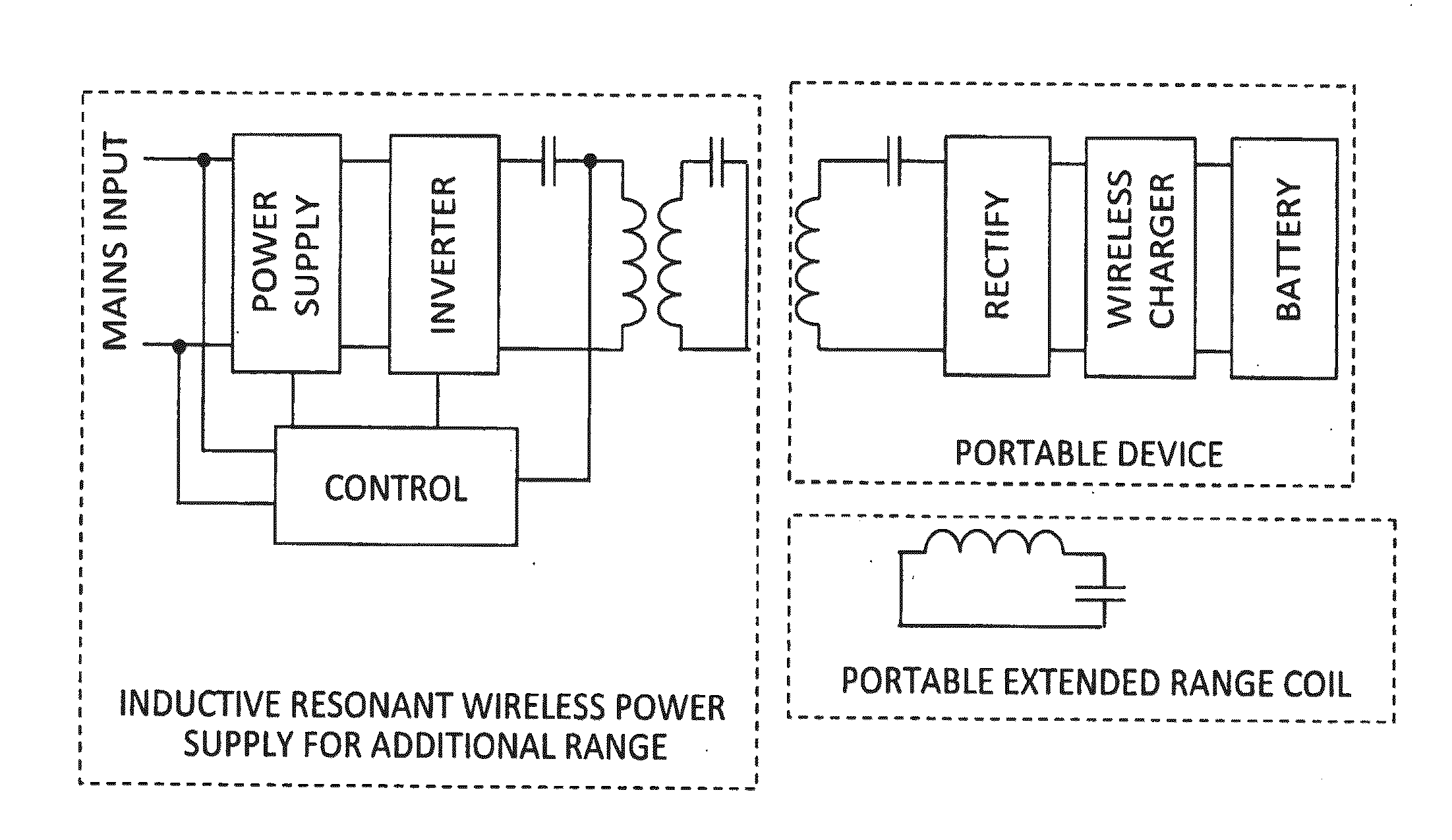
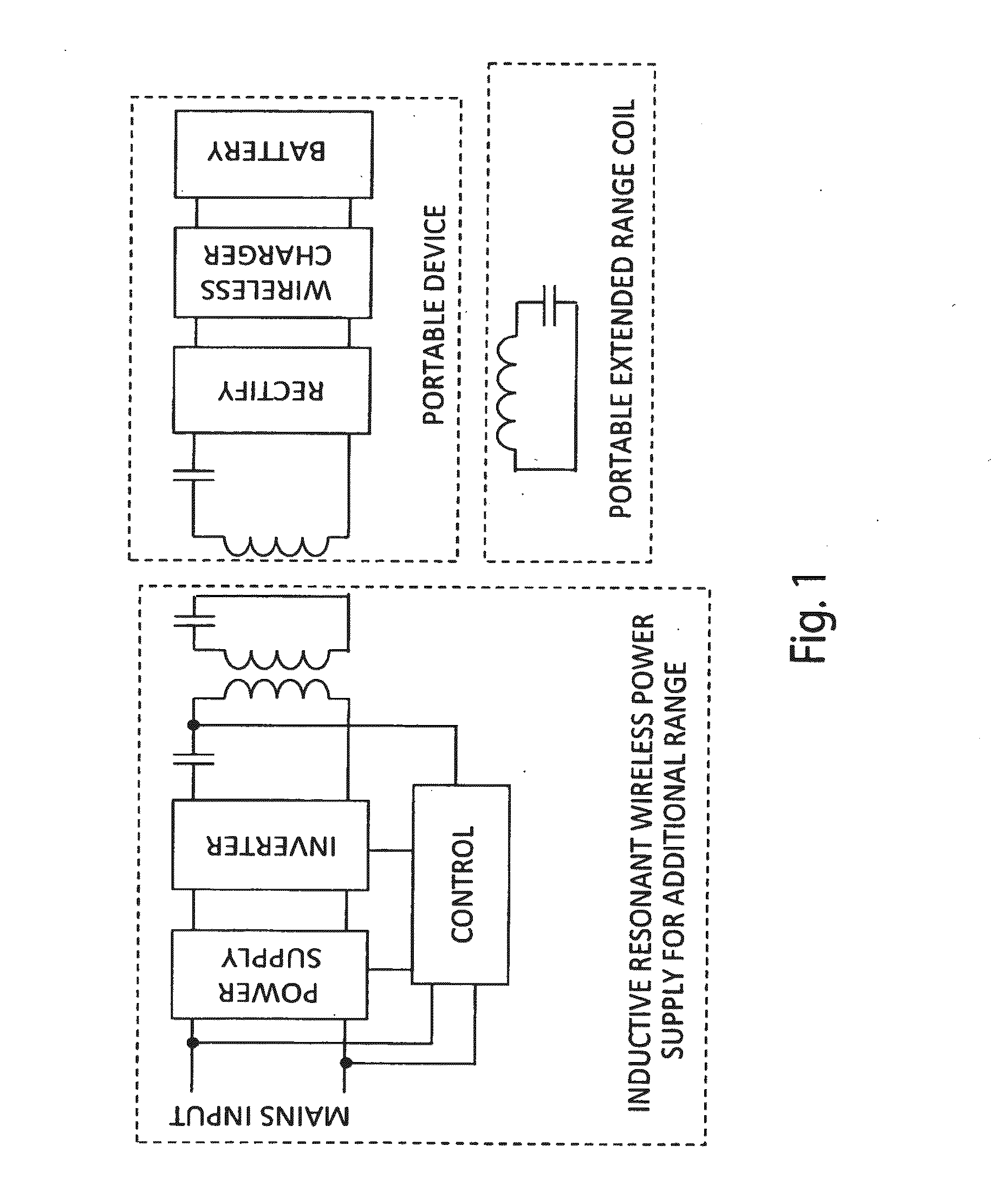
[0113]A behavior modification system in accordance with one embodiment of the present invention is configured to assist a user in improving health and well-being, as well as other objectives that may be set by the user. In one embodiment, the system collects a variety of data and provides a user with feedback based on the collected data. Feedback may include simple feedback, such as reports on the tracked data, and it may include more complicated feedback, such as guidance or assistance in improving health and well-being based on determinations made from analysis of the collected data. In use, the system may collect a wide variety of data, including user data (e.g. biometric data, physiological data, physical activity), environmental data (e.g. temperature, location, sunlight, barometric pressure, elevation, noise level) and other data that might represent behavior, impact behavior or otherwise be relevant to one or more of the objectives of the system. The types of data ...


PUM


Abstract

A behavior modification system includes a network of components that interact to collect various data and provide user feedback. The network may include a personal device, an Internet-enabled storage device and a hub capable of receiving communications from the personal device and communicating to the storage device. The personal device may include bio-impedance measurement circuitry, an accelerometer and a processor for determining energy expenditure based on data from the accelerometer(s). The system may include a smart hub capable of routing communications between various components within the system. The hub may include different transceivers for different communication protocols. The system may incorporate a low-power RF wake-up system. The system may include bio-impedance measurement circuitry that is reconfigurable to function as an alternative type of sensor. In other aspects, the present invention provides a method for measuring bio-resonance and a method for determining caloric intake from body composition and caloric expenditure.

Description

BACKGROUND OF THE INVENTION[0001]The present invention relates to automated systems and methods for understanding and assisting in human behavior, and more particularly to automated systems and methods for collecting a variety of user-related data and providing feedback to the user.[0002]In the past, many have attempted to collect and gather information to aid users in understanding health, behavior and various conditions. These systems have been limited in scope and capabilities, as they have not, among other things, adequately addressed the need to change the behavior of the users. Many systems have been designed to monitor user data and report on specific details. As a result, these types of systems have met with only limited commercial success.I. Energy Expenditure[0003]The most typical form of behavior that consumers seek to understand and control is that of health or weight. Health monitoring devices typically seek to measure caloric expenditure, so that a user may determine a...

Claims


Application Information

Patent Timeline
Patent Type & Authority Applications(United States)
IPC IPC(8): G09B19/00G06F3/01G16H20/30G16H40/67
CPCG09B19/00G06F3/017A61B5/002A61B5/0022A61B5/024A61B5/0537A61B5/1112A61B5/1118A61B5/4833A61B5/4866A61B2560/0209A61B2562/0219A61B5/4875G16H40/67G16H20/30
Inventor BAARMAN, DAVID W.RUNYON, MATTHEW K.LEPPIEN, THOMAS JAYDEAN, CODY D.MOES, BENJAMIN C.KUYVENHOVEN, NEIL W.BURRELL, PATRICK M.WOLFE, TIMOTHY D.B.GUTHRIE, WARREN E.MOELKER, DAVEJOHNSON, RYANVEISEH, MERDAD
Owner ACCESS BUSINESS GRP INT LLC
Why Eureka
Try Eureka