System and Method of Automated Civil Infrastructure Metrology for Inspection, Analysis, and Information Modeling

Inactive Publication Date: 2014-11-13
SCOTT MICHAEL L
View PDF8 Cites 134 Cited by
  • Summary
  • Abstract
  • Description
  • Claims
  • Application Information

AI Technical Summary

Problems solved by technology

Inspection, measurement, evaluation, and documentation of civil infrastructure such as U.S. bridge structures are currently labor intensive tasks.
These tasks are increasingly demanding due to U.S. Federal Government requirements for frequent bridge inspections (at least biannual, [AASHTO, 2011; U.S. Fed. Reg., 2004]) combined with the increasing age and scope of the U.S. infrastructure [Chase, 2003].
These existing techniques include visual

Method used


Image

  • System and Method of Automated Civil Infrastructure Metrology for Inspection, Analysis, and Information Modeling
  • System and Method of Automated Civil Infrastructure Metrology for Inspection, Analysis, and Information Modeling
  • System and Method of Automated Civil Infrastructure Metrology for Inspection, Analysis, and Information Modeling

Examples


first embodiment

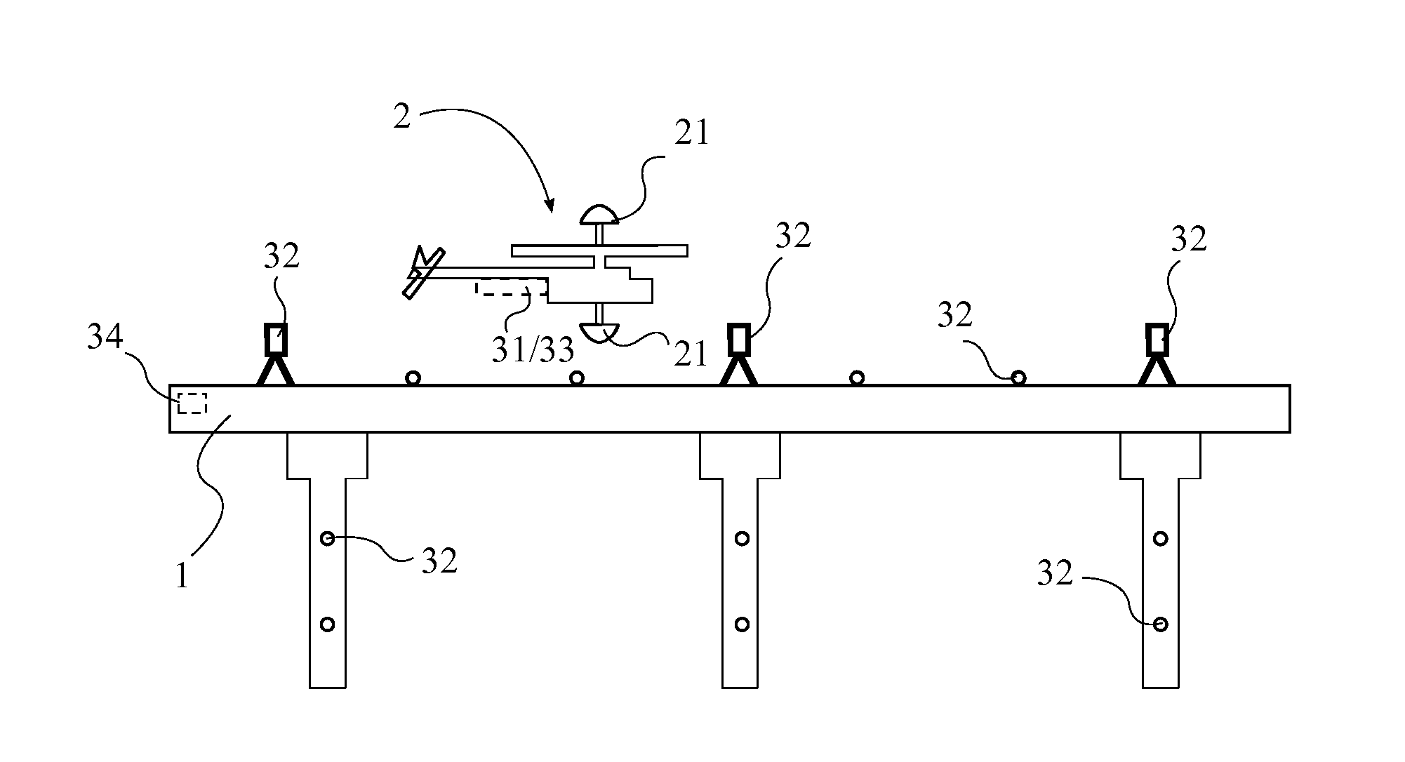
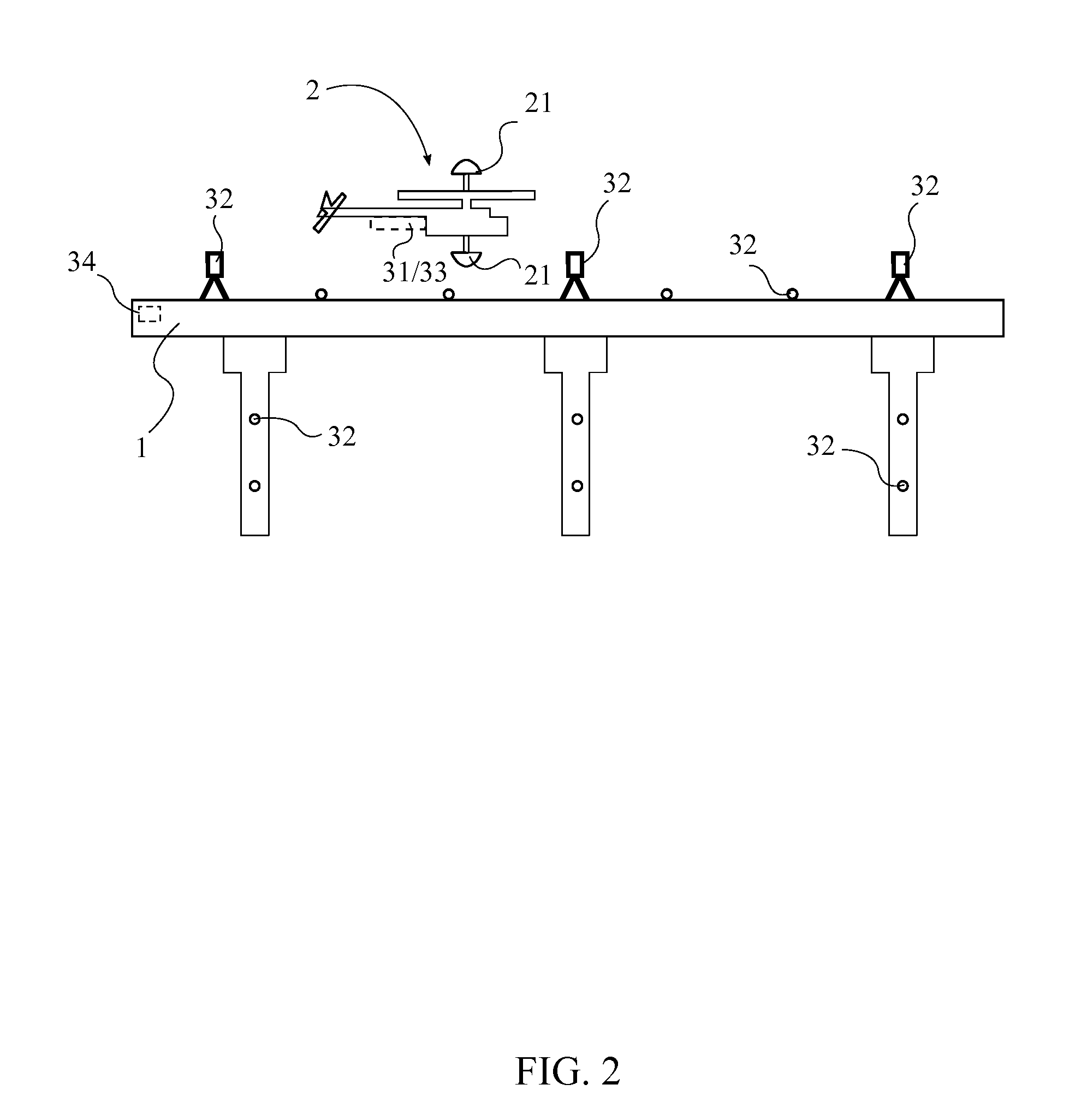
[0030]In the first embodiment comprising iGPS as the position tracking system 3, at least two position indication signals are received by the chipset 23. The at least two position indication signals each correlate to one of the position reference targets 32 distributed on the structure 1. A current position is continually calculated for the UAV 2 from the at least two position indication signals through triangulation. The current position is used to maintain a correct scan pattern while navigating around the structure 1, and additionally the current position is continually associated with one of the plurality of images, wherein the one of the plurality of images is the newest image taken. The current position is defined according to a coordinate system containing the structure 1. The iGPS can be used to measure the relative position of image features within better than survey accuracy (<1 mm in three dimensions) based on images that include iGPS targets. ACMS uses this data to build...

second embodiment

[0031]In the second embodiment comprising the VIO system as the position tracking system 3, an initial position signal is initially received. The initial position serves as a zero or calibration point for the position tracking system 3. During flight, inertial measurement signals are continually produced by the IMU 33 and continually received by the navigation system, wherein the inertial measurement signals indicate linear and angular accelerations for the UAV 2, which are used to calculate changes in velocity and position. The current position is continually calculated for the UAV 2 from the initial position signal and the inertial measurement signals.

[0032]After the plurality of images is collected, the plurality of images is transferred to the database for post processing. In post-processing, the pattern recognition and image analysis algorithms are used to detect a plurality of structure 1 features in the plurality of images, wherein the structure 1 features may include, but ar...


PUM


Abstract

A system and method of automated civil infrastructure metrology for inspection, analysis, and information modeling utilizes an unmanned aerial vehicle (UAV) equipped with a position tracking system and digital cameras to capture a plurality of images of a structure to be inspected. The UAV is flown in a scan pattern around the structure while continually capturing images of the structure while position and orientation data is also recorded and linked for each of the images. Image processing and pattern recognition software algorithms are used to analyze the images and create an information model of the structure which is then used to carry out a virtual inspection of the structure in a three dimensional software environment.

Description

[0001]The current application claims a priority to the U.S. Provisional Patent application Ser. No. 61 / 821,755 filed on May 10, 2013. The current application is filed in the U.S. on May 12, 2014 while May 10, 2014 was on a weekend.FIELD OF THE INVENTION[0002]The present invention relates generally to inspection of civil infrastructure. More particularly, the present invention relates to an automated civil infrastructure metrology system for inspection and evaluation of bridges, dams, buildings and other structures.BACKGROUND OF THE INVENTION[0003]Inspection, measurement, evaluation, and documentation of civil infrastructure such as U.S. bridge structures are currently labor intensive tasks. These tasks are increasingly demanding due to U.S. Federal Government requirements for frequent bridge inspections (at least biannual, [AASHTO, 2011; U.S. Fed. Reg., 2004]) combined with the increasing age and scope of the U.S. infrastructure [Chase, 2003].[0004]A need exists for an automated tec...

Claims


Application Information

Patent Timeline
IPC IPC(8): G01N21/88B64C13/00
CPCG01N21/88B64C13/00B64C2201/145G01M5/0008G01M5/0033G01M5/0091G01C21/206B64U2101/30G01C21/1656
Inventor SCOTT, MICHAEL L.
Owner SCOTT MICHAEL L
Why Eureka
Try Eureka