Rotary pulse detonation engine

Inactive Publication Date: 2014-11-20
POMERLEAU DANIEL GUY
View PDF19 Cites 5 Cited by
  • Summary
  • Abstract
  • Description
  • Claims
  • Application Information

AI Technical Summary

Benefits of technology

[0021]In yet another aspect, the invention provides improvements in a jet engine having a combustion chamber, turbine and compression stages and an exhaust nozzle, the improvement comprising a rotary pulse detonation engine (RPDE) operatively configured to the combustion chamber for directing detonation exhaust from the RPDE against turbine blades of the turbine stage.
[0022]In another aspect, the invention provides improv

Problems solved by technology

Even while inside the engine the mixture's volume is continually changing, which is an inefficient way to burn fuel.
Thus, the amount of heat produced per unit of fuel is generally higher than other engines, although in most PDE designs, conversion of that energy into thrust remains inefficient due to various restrictions/constrictions within the typical PDE engine.
Another problem with PDEs is that current designs use detonation waves to compress the fuel/air within the detonation chamber in order to increase the pressure, density and temperature of the fuel/air.
Further still, PDEs have chamber temperatures in the order of 3,500° F. which tends to cause premature failures of engine parts.
Also, initiating repetitive detonations is a problem.
Another limitation of a traditional pulsejet engine is that the pulse frequency is maximal at about 250 pulses per second due to the cycle time of the mechanical shutters.
Unfortunately, detonation explosions are generally much louder than deflagration combustion.
As noted above, one significant problem with a pulse-detonation engine is starting the detonation.
While it is

Method used


Image

  • Rotary pulse detonation engine
  • Rotary pulse detonation engine
  • Rotary pulse detonation engine

Examples


Example

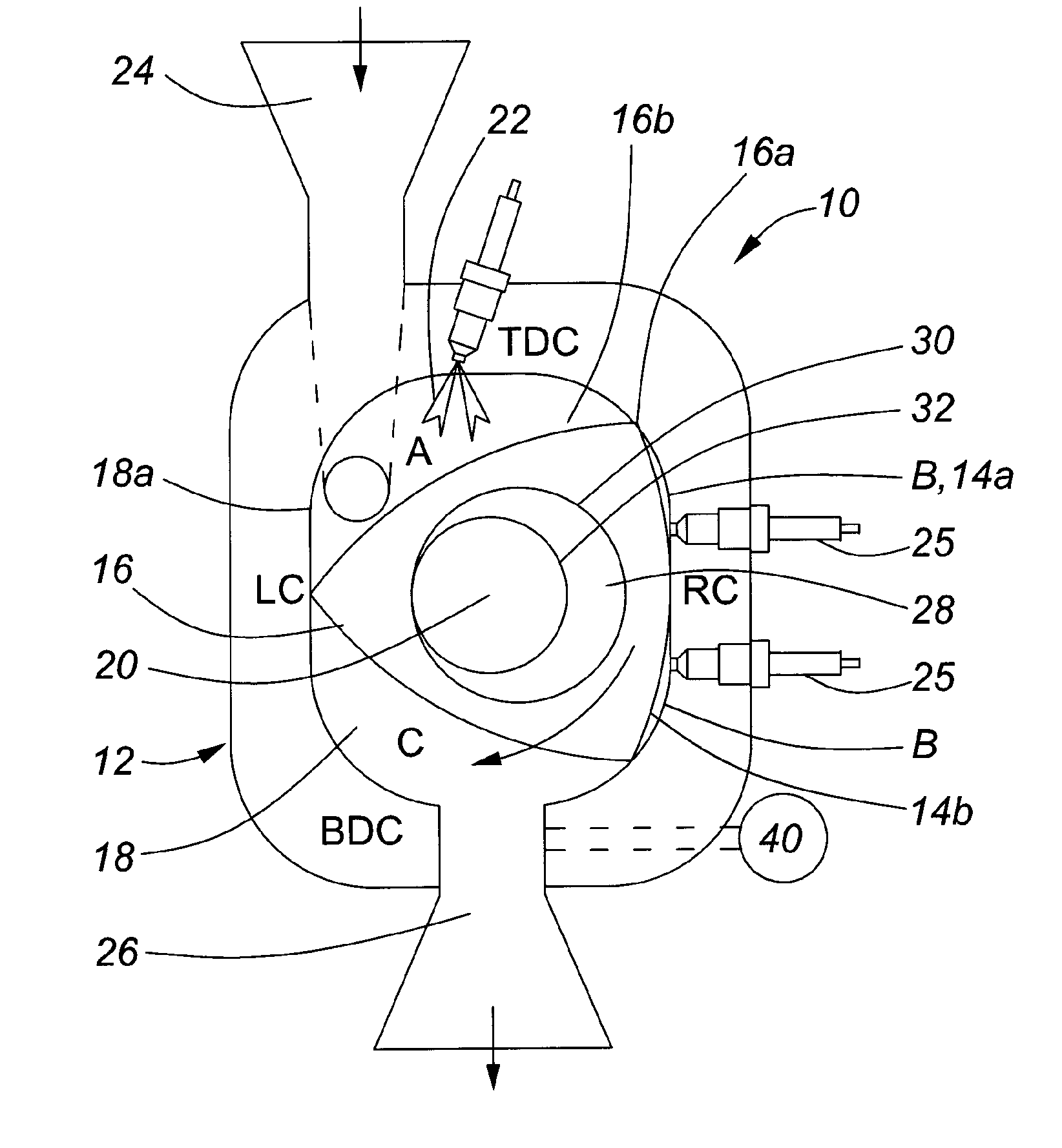
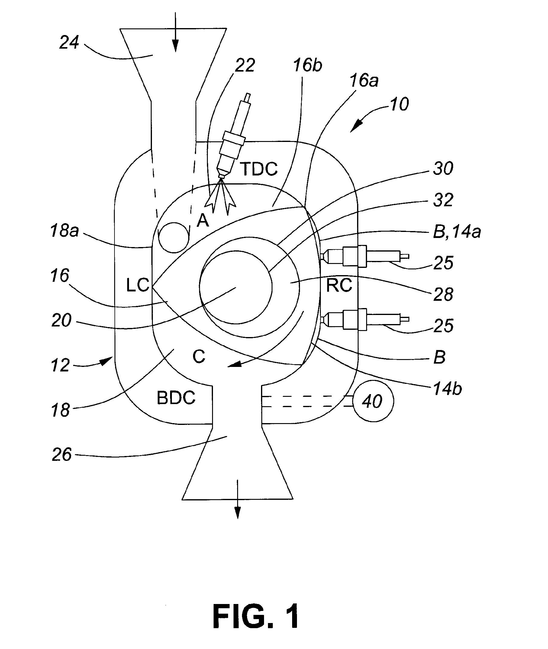
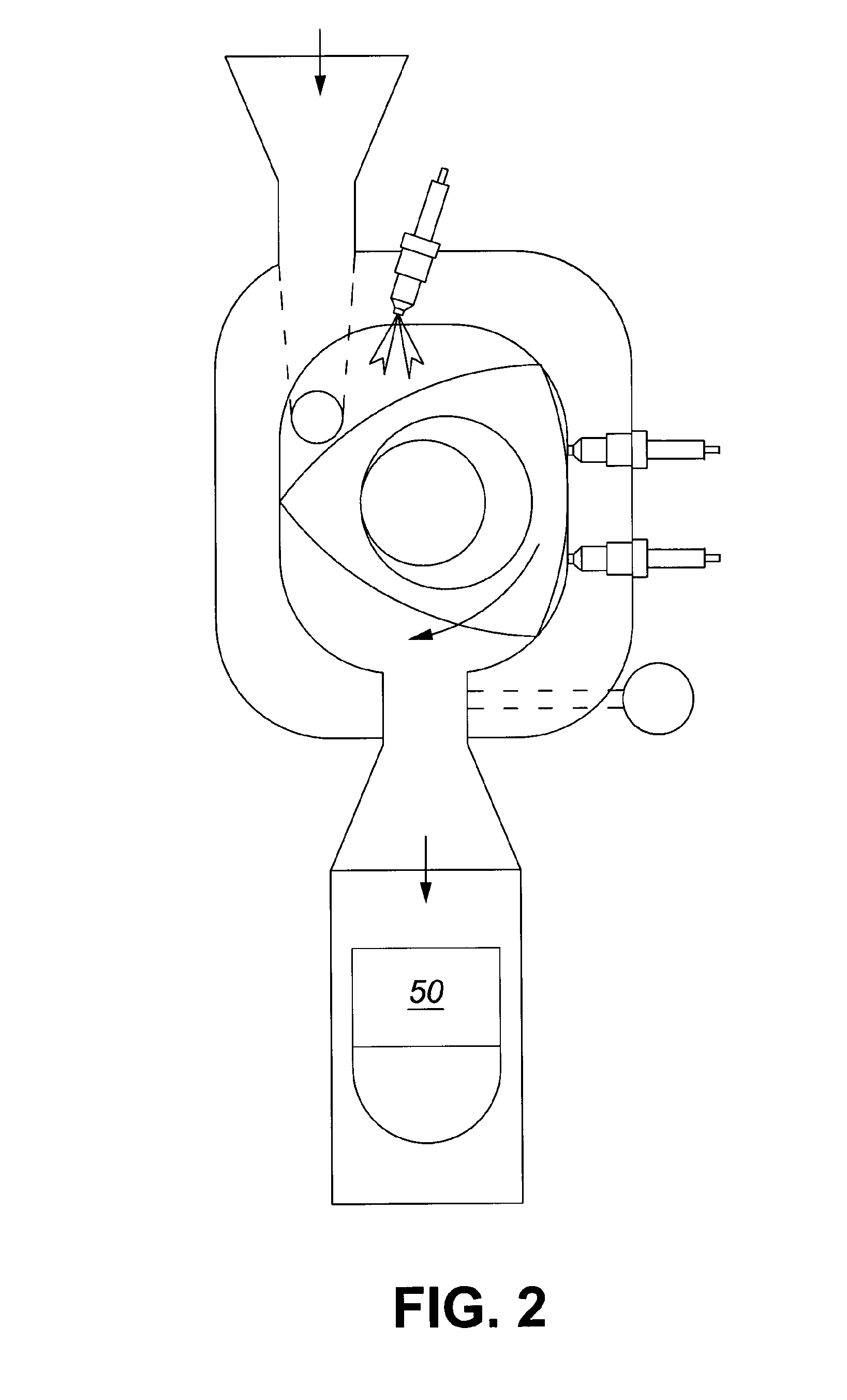
[0033]With reference to the figures, a pulse detonation engine (PDE) is described having a rotating valve for high temperature and high pressure operation in a pulse detonation combustor.

[0034]As shown in FIG. 1, the PDE 10 utilizes a rotary valve 12 and combustion chamber 14a, 14b of a Wankel-type rotary engine as the means for generating pulsed detonations of pressurized fuel / air.

[0035]More specifically, as is known, a Wankel-type engine is a variable volume processing cavity system in which a lobed rotor 16, having rotor tips 16a and rotor surfaces 16b is rotated within a generally oval chamber 18 having chamber walls 18a. As the lobed rotor is caused to rotate within the chamber about a central axis 20, the rotor tips trace the circumference of the oval chamber such that the rotor surfaces successively move towards and away from the oval chamber walls thereby defining different volumes at different locations within the chamber as the rotor progresses through a complete rotation....


PUM


Abstract

This invention relates to devices for discharging high pressure exhaust, and in particular to pulse detonation engines. More specifically, the invention describes a rotary pulse detonation engine having a rotary valve system. The rotary valve includes a generally-triangular rotor having rotor tips within a rotor chamber having trochoid inner end surfaces and side surfaces. The rotor defines three working chambers defined by the rotor tips contacting the rotor surfaces. In operation, the rotor tips move in a circumferential direction around the rotor chamber as the rotor spins. During operation, each of the working chambers will sequentially pass through an intake interval, compression interval, expansion interval, and an exhaust interval to create and detonate compressed fuel air mixtures for effective release to an exhaust chamber and nozzle thereby creating a pulsed detonation sequence.

Description

FIELD OF THE INVENTION[0001]This invention relates to devices for discharging high pressure exhaust, and in particular to pulse detonation engines. More specifically, the invention describes a rotary pulse detonation engine having a rotary valve system. The rotary valve includes a generally-triangular rotor having rotor tips within a rotor chamber having trochoid inner end surfaces and side surfaces. The rotor defines three working chambers defined by the rotor tips contacting the rotor surfaces. In operation, the rotor tips move in a circumferential direction around the rotor chamber as the rotor spins. During operation, each of the working chambers will sequentially pass through an intake interval, compression interval, expansion interval, and an exhaust interval to create and detonate compressed fuel air mixtures for effective release to an exhaust chamber and nozzle thereby creating a pulsed detonation sequence.BACKGROUND OF THE INVENTION[0002]All regular jet engines and most ro...

Claims


Application Information

Patent Timeline
IPC IPC(8): F02K7/06F02K9/97
CPCF02K7/06F05D2220/80F02K9/97F01C1/22F02C3/14F02C5/02F23R7/00F02C3/085F02C5/06F02K7/02
Inventor POMERLEAU, DANIEL GUYHICKS, ANDREW RICHARD
Owner POMERLEAU DANIEL GUY
Why Eureka
Try Eureka