
Photovoltaic textiles

a technology of photovoltaic textiles and textiles, applied in the field of textiles, can solve the problems of significant voltage drop in available electricity, insufficient thickness for efficient charge transport, and inability to produce efficient solar textiles from existing ppv components, etc., and achieve the effect of low contact resistance and large electrical contact area

Inactive Publication Date: 2014-11-20
PARENT DONALD G +1
View PDF6 Cites 9 Cited by
  • Summary
  • Abstract
  • Description
  • Claims
  • Application Information

AI Technical Summary

Benefits of technology

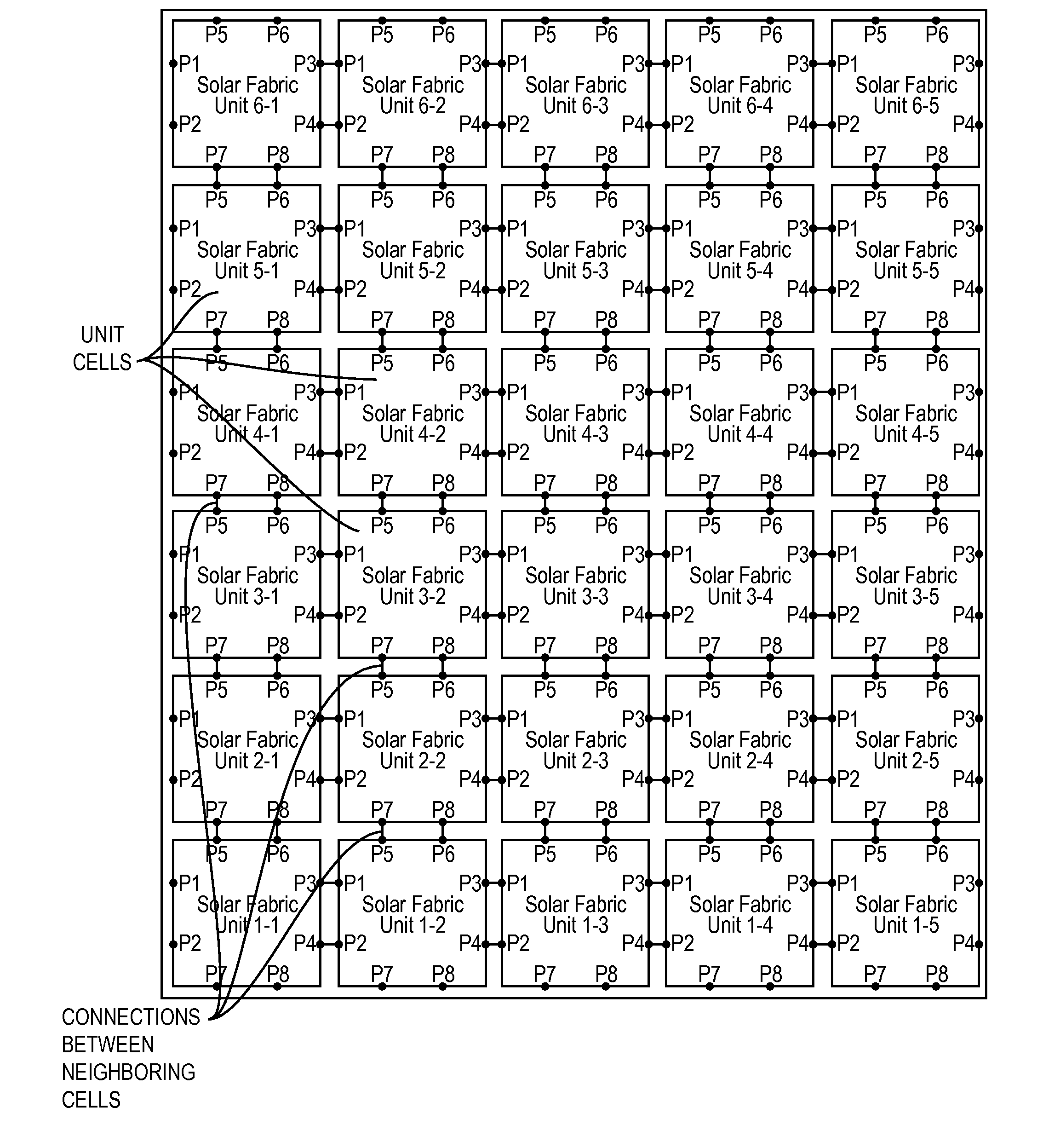
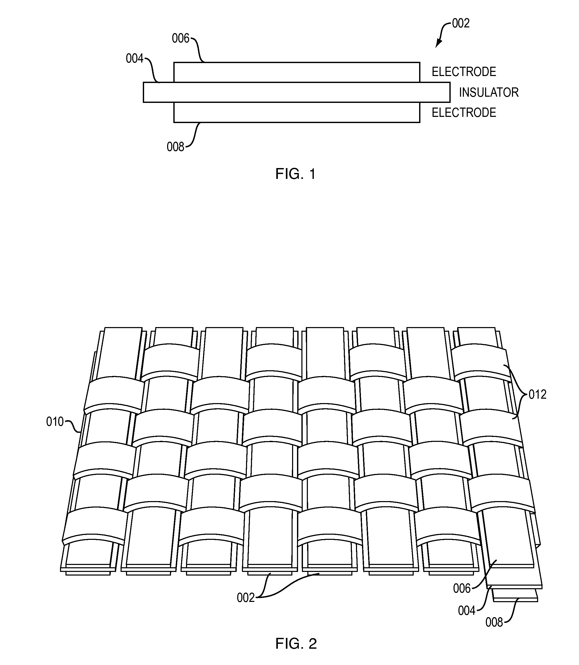
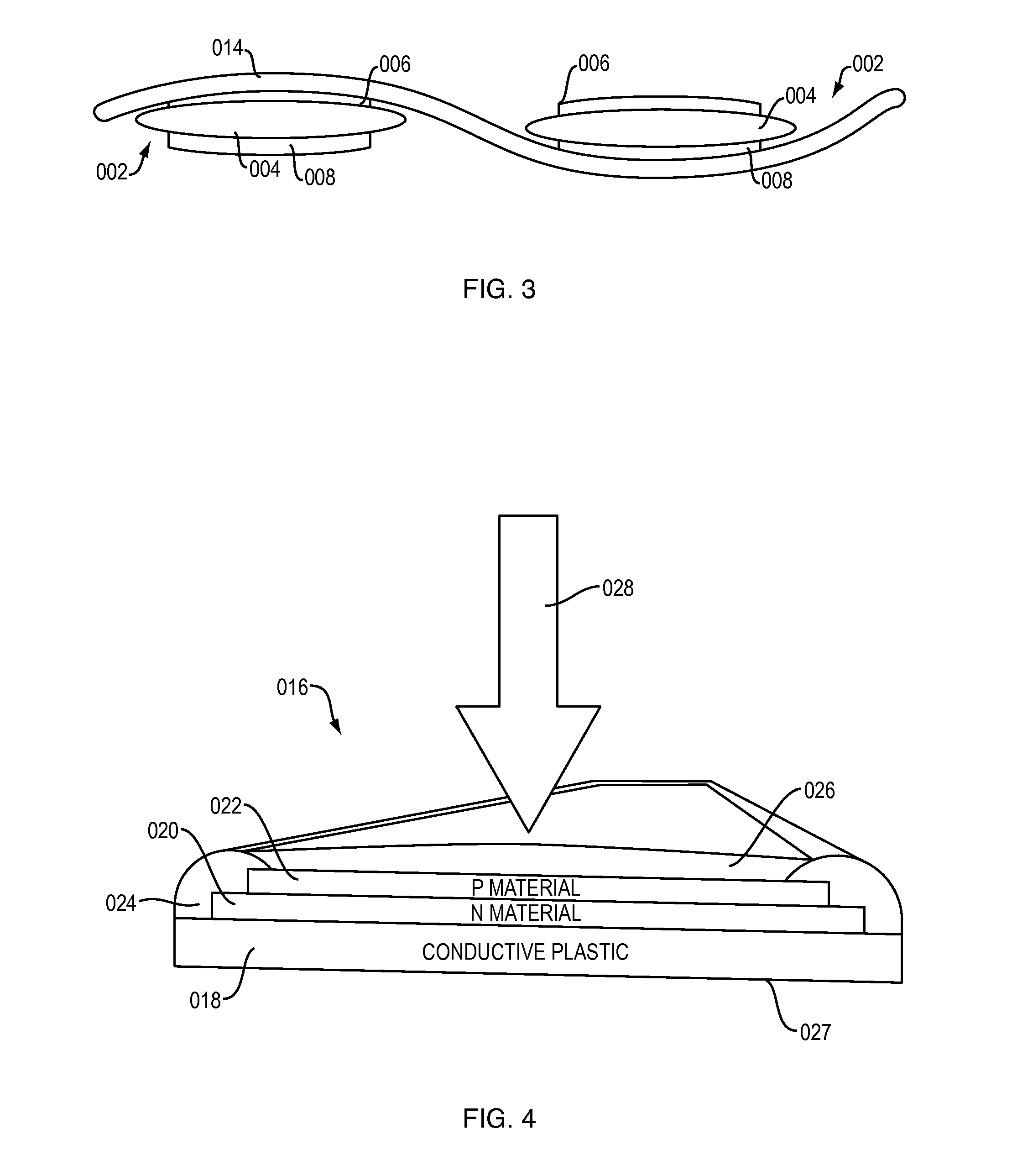
The present invention is about improving solar textile performance by using a systems approach to the overall design. The textiles use highly conductive bus bars that serve as conduits in contact with elongated photovoltaic components to move charge in and out of the textile unit cells. This minimizes charge transport resistance throughout the textile by providing multiple, durable electrical contacts with charged surfaces along the length of the photovoltaic components. This results in higher efficiency and performance of the solar textiles.

Problems solved by technology

However, attempts at producing efficient solar textiles from existing PPV components have been constrained by fundamental technical barriers relating to their inherent electrical resistance.
However, when such fibers are incorporated into a textile, the low electrical conductivity of the external, optically transparent electrode causes significant voltage drop in the available electricity.
However, efficient charge transport requires sufficient thickness to provide a low electrical resistance path.
Currently available optically transparent compounds, such as ITO and many of the new polymer-based substances such as PEDOT, do not simultaneously satisfy the optical clarity and electrical conductivity requirements.
For PPV components made from these substances, acceptable optical transmission results in excessive electrical sheet resistance for use in solar textiles.
However, the movement of power through textiles made from such fibers is generally more complicated and less reliable because of the need to make and maintain additional electrical connections with external circuitry.
Furthermore, the small cross sectional dimension typical of internal conductors restricts charge flow.
Similar to co-axial fibers, charge transport along the axis of dual internal conductor fibers yields large voltage drop, thereby diminishing the performance of textiles in which such fibers are used.
In addition to poor efficiency, solar textile modules made from photovoltaic fibers known in the art are subject to malfunction from shorting of conductors, particularly at connections where charges from multiple fibers are merged.
Unless substantially fortified, the delicate nature of the small connections allows them to be damaged from minor impacts or abrasions.
Depending on the design, a single short circuit could impair the function of multiple cells, or even adjacent solar modules.
Similarly, solar textile modules made from other existing photovoltaic components such as thin films are either too fragile or rigid and are still largely unproven for exploiting the advantages of solar textiles.
These and other technical problems relating to existing photovoltaic components and systems continue to inhibit the rapid commercialization of new applications for solar textiles.

Method used


Image

  • Photovoltaic textiles
  • Photovoltaic textiles
  • Photovoltaic textiles

Examples


Embodiment Construction

[0057]As used herein the term “converting means” refers to a component that is photovoltaic or otherwise produces electricity when exposed to electromagnetic radiation.

[0058]The term “deposit” covers all technologies used in coating a surface with a material including but not limited to spraying, dipping, spin coating, vacuum and chemical deposition, printing including, but not limited to, inkjet printing.

[0059]The term “electrical appliance” refers to a component that is made operable in function or capacity by current including but not limited to cell phones, global positioning systems, lights, motors, batteries, regulators, inverters, rectifiers, and transformers.

[0060]The term “interlaced” means going one over the other as to be woven or intertwined in uniform structure and geometry.

[0061]The term “integral” means fixed or made a part of during the manufacturing process.

[0062]The term “light” includes a range of electromagnetic radiation known as visible light and portions of in...


PUM


Abstract

Textile systems and components for establishing electrical characteristics of textiles. The textiles incorporate charge carrying components, such as photovoltaic components, in contact with highly conductive bus conduits to improve electrical properties without compromising physical characteristics of the textiles. Structure, geometries, and methods are provided for textile constructs, including photovoltaic textile constructs.

Description

BACKGROUND OF THE INVENTION[0001]1. Field of the Invention[0002]This invention relates to textiles designed for converting electrical charges, such as charges generated through solar energy, into usable electricity. More specifically the invention is directed to electrical charge transfer textiles, photovoltaic systems, solar textiles, and sub-components which reduce electrical resistance for improved performance.[0003]2. Description of Related Art[0004]Photovoltaic systems convert sunlight into electricity through the action of photovoltaic cells. Large solar arrays currently in use typically have numerous panels or modules, each with many photovoltaic cells. Such arrays have been made from rigid components. More recently, flexible photovoltaic components have been developed that may be incorporated into textiles as alternatives to rigid cells and modules.[0005]Flexible solar energy technology holds great promise for many applications. The freedom of movement provided by fabrics ha...

Claims


Application Information

Patent Timeline
Patent Type & Authority Applications(United States)
IPC IPC(8): H02S30/20H01L31/02
CPCH01L31/0201H01L31/045H02S30/20Y02E10/50
Inventor PARENT, DONALD G.GUVENCH, MUSTAFA G.
Owner PARENT DONALD G
Learn More