Emulsion-producing hydraulic circuit and method for re-emulsifying a separated liquid

a technology of emulsion-producing hydraulic circuit and separated liquid, which is applied in the direction of positive displacement liquid engine, machine/engine, transportation and packaging, etc., can solve the problems of unstabilized water portion, natural separation, damage or unintended, etc., to simplify the installation and operation of water emulsion, increase the protection of pump seal, and facilitate maintenance and operation

Inactive Publication Date: 2014-11-27
CAVITRONIX CORP
View PDF1 Cites 1 Cited by
  • Summary
  • Abstract
  • Description
  • Claims
  • Application Information

AI Technical Summary

Benefits of technology

[0012]As described herein, the present invention relates to a hydraulic circuit comprising an asynchronous loop to skim off a portion of any slug of water existing in the hydraulic circuit and inject it into the return line where the emulsion is being continuously returned. This asynchronous by-pass loop, which is nested within the normal supply / return line, also serves as a redundant, or back-up, by-pass function, increasing pump seal protection as well as enabling asynchronous remixing of water back into an emulsion.
[0013]Moreover, the present invention simplifies installation and operation of water emulsions, including FOE systems. For example, in one embodiment where it is physically possible to do so, all piping circuits may be bored into a single block of metal or other water and fuel resistant material with all necessary components mounted to or affixed thereon. A single block creates an easily maintainable and operational system that simplifies the device operation and care ensuring it can continue to be used for the purposes intended, including the reduction of basic fuel oil consumed and reduction of pollution created by the combustion process.

Problems solved by technology

Installing, measuring, and / or controlling, inflows of fuels and water and, in some cases, chemical additives, into cavitational and other mechanical blenders and emulsifiers as well as outflows of fuel-oil emulsion (“FOE”) is currently uncertain with existing FOE technology, because existing FOE devices are not easily integrated into the existing combustion engine, turbine, or boiler system.
The challenge in existing FOE technology and certain other emulsions is that the water portion of un-stabilized emulsions, including water-in-oil FOE, which is created for use in burners, boilers, turbines, and combustion engines, begins to separate naturally when the emulsifying system stops operating during shut-downs.
De-emulsified accumulations in the hydraulic circuit that are injected into a burner, boiler, turbine, or combustion engine (or elsewhere) could cause damage or unintended results.
This water slug, if not re-emulsified but injected as plain water into the boiler, could quench a flame and potentially damage fire tubes or combustion chambers, or if injected into a combustion engine could damage the piston and / or other critical engine parts.

Method used


Image

  • Emulsion-producing hydraulic circuit and method for re-emulsifying a separated liquid
  • Emulsion-producing hydraulic circuit and method for re-emulsifying a separated liquid
  • Emulsion-producing hydraulic circuit and method for re-emulsifying a separated liquid

Examples


Embodiment Construction

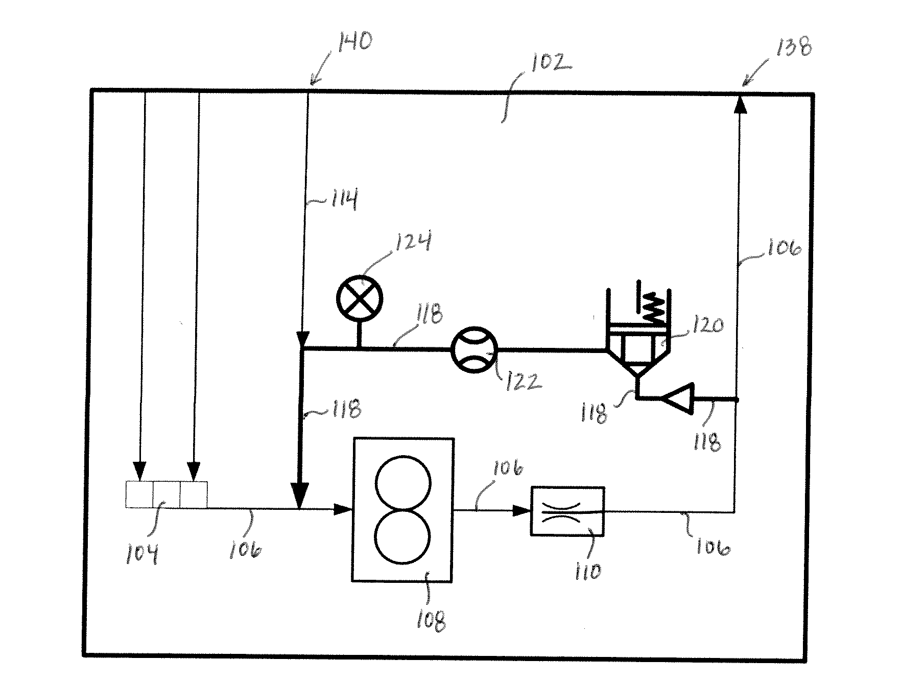
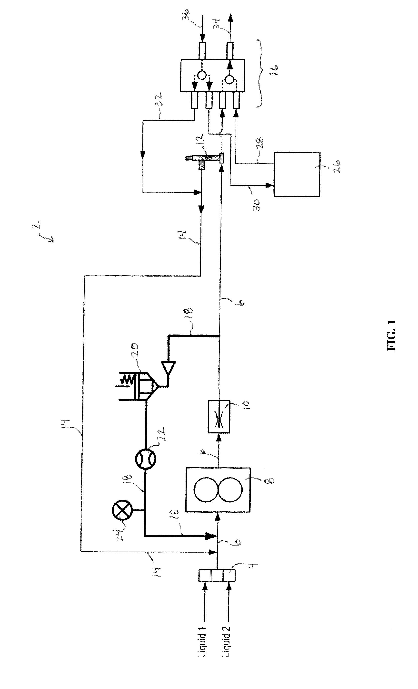
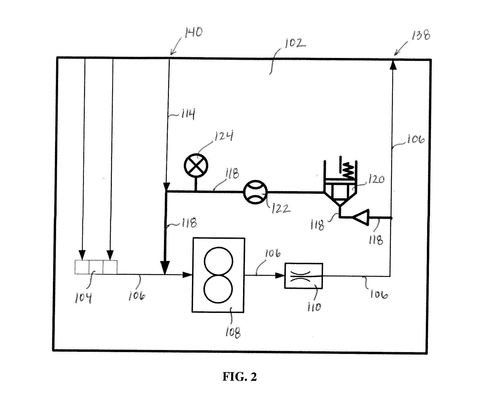
[0017]The present invention relates to an emulsion-producing hydraulic circuit comprising an intake port for receiving at least two liquids; a supply line comprising a first end and a second end, wherein the first end of the supply line is connected to the intake port to receive and transport the at least two liquids; a pump positioned in the supply line to create flow of the at least two liquids through the hydraulic circuit; an emulsion-producing device positioned in the supply line and capable of forming an emulsion of the at least two liquids; a fitting connected to the second end of the supply line, where the fitting receives the emulsion and transfers (i) a first portion of the emulsion from the hydraulic circuit to a combustion site and (ii) a second portion of the emulsion to a return line, where the return line comprises a first end and a second end, the first end of the return line being connected to the fitting and the second end of the return line being connected to the ...


PUM

PropertyMeasurementUnit
sizeaaaaaaaaaa
sizeaaaaaaaaaa
pressureaaaaaaaaaa

Abstract

The present invention relates to an emulsion-producing hydraulic circuit. The hydraulic circuit includes a by-pass loop comprising a first end and a second end, where the first end of the by-pass loop and the second end of the by-pass loop are connected to a supply line of the hydraulic circuit before and after a pump. The asynchronous by-pass loop also includes a control valve, and the by-pass loop transfers a portion of an emulsion and/or any separated liquid that has accumulated in the hydraulic circuit to the supply line to be re-emulsified. Also disclosed is a method for re-emulsifying a separated liquid present in a hydraulic circuit.

Description

[0001]This application claims the benefit of U.S. Provisional Patent Application Ser. No. 61 / 532,953, filed Sep. 9, 2011, which is hereby incorporated by reference in its entirety.FIELD OF THE INVENTION[0002]The present invention relates to an emulsion-producing hydraulic circuit and a method for re-emulsifying a separated liquid present in a hydraulic circuit.BACKGROUND OF THE INVENTION[0003]Emulsion fuels have been shown to have environmental and, in some cases, cost benefits over basic fuel oil. Installing, measuring, and / or controlling, inflows of fuels and water and, in some cases, chemical additives, into cavitational and other mechanical blenders and emulsifiers as well as outflows of fuel-oil emulsion (“FOE”) is currently uncertain with existing FOE technology, because existing FOE devices are not easily integrated into the existing combustion engine, turbine, or boiler system.[0004]Installation and control of inflows and outflows of water emulsions, including FOE systems, c...

Claims


Application Information

Patent Timeline
Patent Type & Authority Applications(United States)
IPC IPC(8): B01F5/10B01F3/08
CPCB01F3/088B01F5/102F02M25/0228Y10T137/86171Y02T10/12B01F23/41B01F23/49B01F25/51
Inventor MARKERT, CHARLES D.
Owner CAVITRONIX CORP
Why Eureka
Try Eureka