Segmented orbital drill

a drill bit and segmental technology, applied in the field of segmental drill bit, can solve the problems of low inter-laminar strength, poor tool life, and accelerated wear on the tool edges, and achieve the effect of increasing the tool life and accelerating the wear of the tool edges

Active Publication Date: 2014-11-27
KENNAMETAL INC
View PDF6 Cites 2 Cited by
  • Summary
  • Abstract
  • Description
  • Claims
  • Application Information

AI Technical Summary

Benefits of technology

This patent describes a way to make tools last longer when machining materials like composite stacks. They do this by using special shapes on the tool edges to increase their lifespan. This results in a segmented orbital drill that can better withstand wear and tear while machining these materials.

Problems solved by technology

FRP materials have excellent in-plane strength, but low inter-laminar strength.
The major issue of machining composite stack materials is the accelerated wear that occurs on the tool edges.
Tool life is very poor, even with advanced substrates and coatings.

Method used


Image

  • Segmented orbital drill
  • Segmented orbital drill
  • Segmented orbital drill

Examples


Embodiment Construction

[0011]Below are illustrations and explanations for a version of combination end milling drilling / push drilling cutting tool and a method for machining a workpiece. However, it is noted that combination cutting tool and machining method may be configured to suit the specific application and is not limited only to the example in the illustrations.

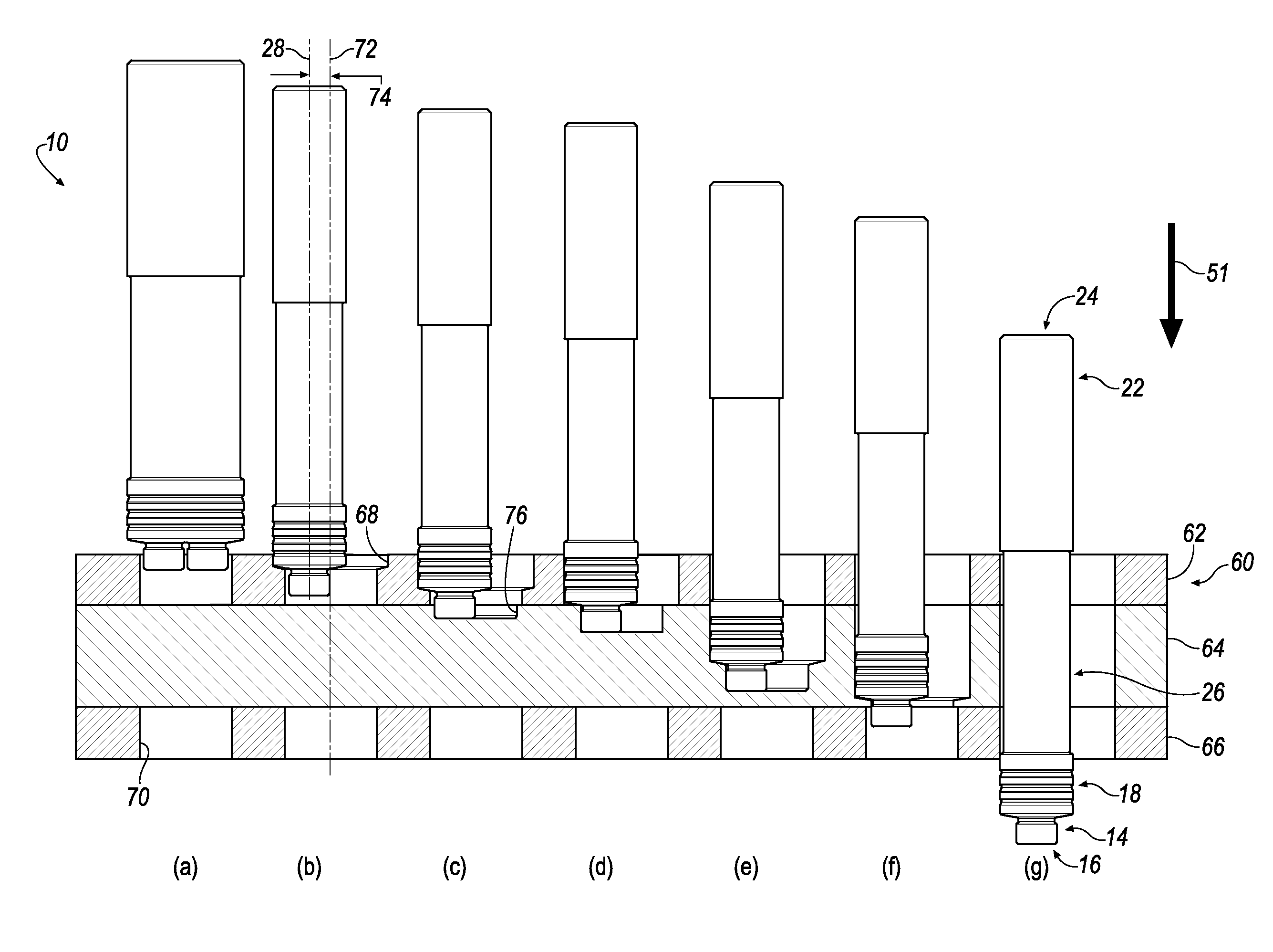
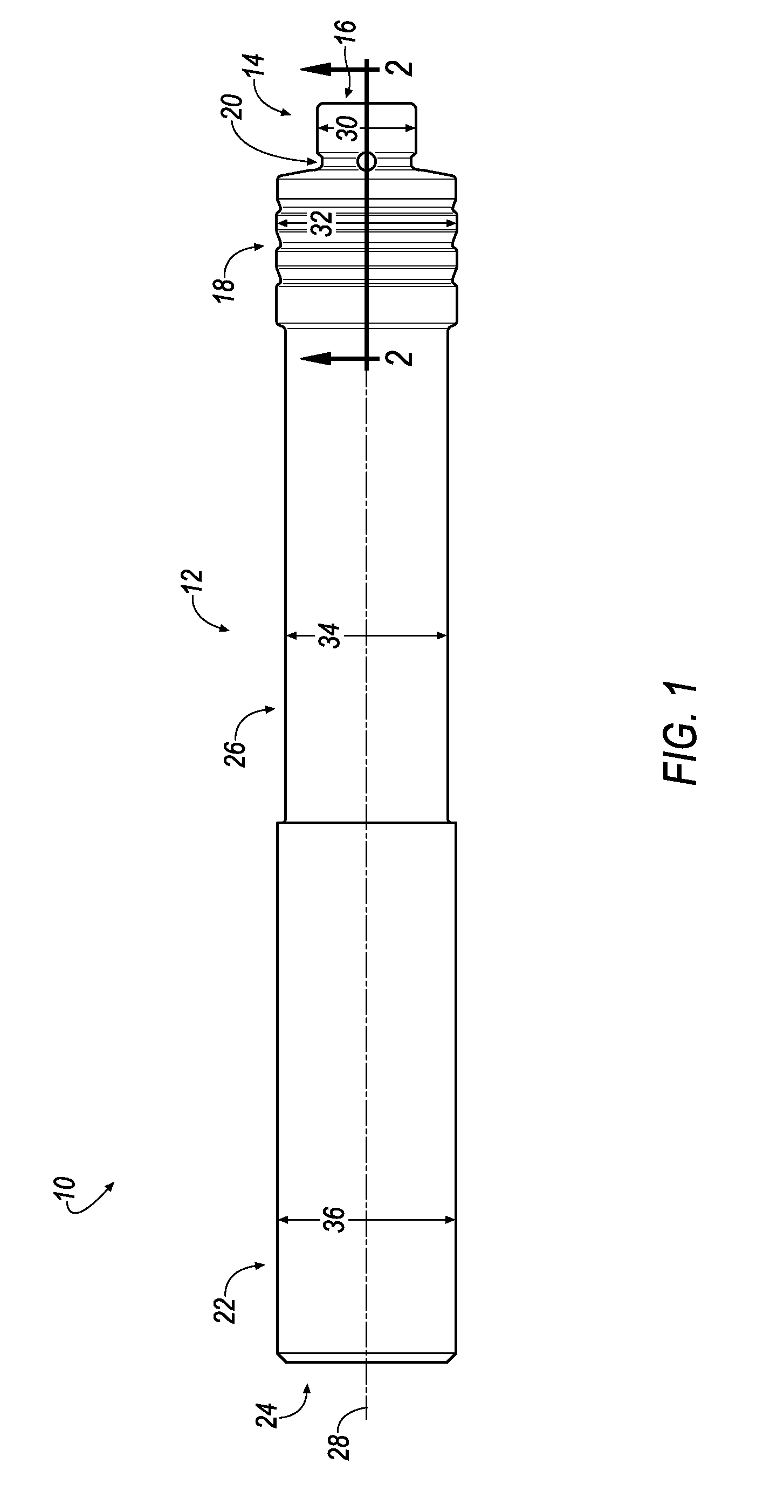
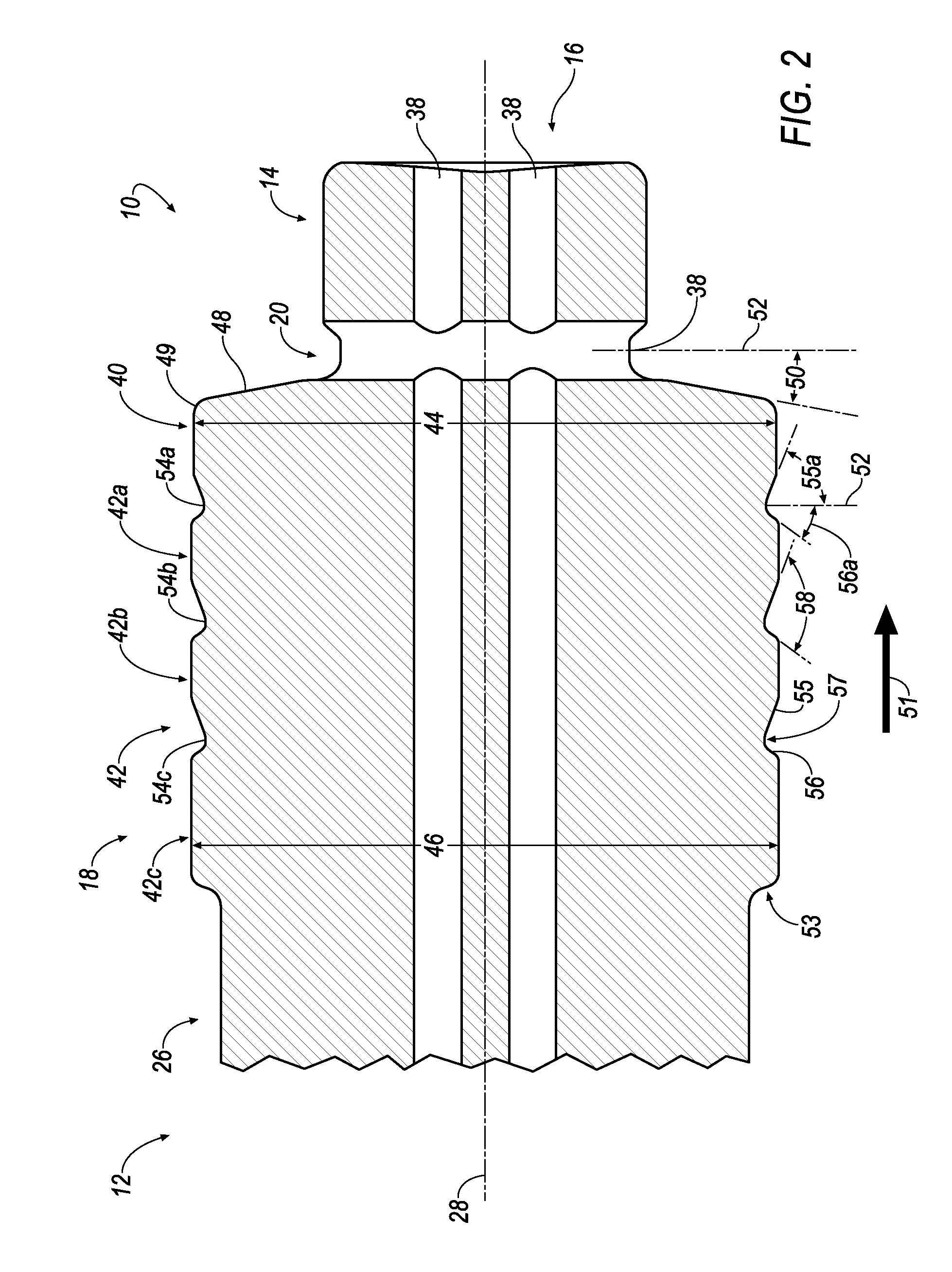
[0012]Referring to FIGS. 1-4, wherein like reference characters represent like elements, a segmented orbital drill for performing a machining operation on a workpiece is generally shown at 10. In one embodiment, the workpiece 60 (FIG. 3) is a composite stack material having a top layer, 62 a middle layer 64 and a bottom layer 66. The top and bottom layer 62, 66 may comprise, for example, a metal, such as titanium, and the like. The middle layer 64 may comprise a different material than the top and bottom layer 62, 66. For example, the middle layer 64 may comprise a carbon fiber reinforced plastic (CFRP) material, and the like. As used herein,...


PUM


Abstract

A segmented orbital drill includes a segmented portion with a semi-finishing cutting portion and a plurality of finishing cutting portions. The semi-finishing cutting portion and finishing cutting portions are separated by grooves formed by a front wall and a rear wall. The segmented portion allows for a fresh cutting edge (i.e., rear wall of the groove) to be revealed as the orbital drill wears in the axial direction. The segmented portion also causes less contact with the workpiece, which reduces power consumption and minimizes deflection of the orbital drill. The segmented orbital drill also includes an optional pilot at one end of the drill, and a clearance neck portion between a shank and the segmented portion. A method of machining a workpiece using the segmented orbital drill is also disclosed.

Description

BACKGROUND OF THE INVENTION[0001]Fiber reinforced plastic (FRP) materials are widely used in aerospace industry due to its high specific strength and high specific stiffness. FRP materials are composite materials consisting of soft resin matrix and high strength fiber reinforcement. Typical fiber reinforcements include carbon fibers (CFRP), glass fibers (GFRP), Kevlar fibers, and the like. FRP materials are often processed into a laminated structure. FRP materials have excellent in-plane strength, but low inter-laminar strength.[0002]Multi-function end effectors, portable orbital machines and CNC machines produce orbital (helically interpolated) holes and / or conventionally drilled holes in composite stack materials.[0003]The major issue of machining composite stack materials is the accelerated wear that occurs on the tool edges. Tool life is very poor, even with advanced substrates and coatings.SUMMARY OF THE INVENTION[0004]The problem of accelerated wear of tool edges when machinin...

Claims


Application Information

Patent Timeline
Patent Type & Authority Applications(United States)
IPC IPC(8): B23B35/00
CPCB23B35/00B23B2220/08B23B2226/275B23B2251/60B23B2270/54B23B2251/245B23B2226/61B23C5/10B23C2210/247B23C2210/70B23C2220/52B23C2226/27Y10T408/9065Y10T407/19Y10T407/1962Y10T408/03Y10T407/195Y10T408/906Y10T409/303808B23C3/02B23B51/009
Inventor CRAIG, KAREN ANNE
Owner KENNAMETAL INC
Why Eureka
Try Eureka