Fuel cell system and method for driving same

a fuel cell and system technology, applied in the direction of fuel cells for electrolyte, electrochemical generators, sustainable buildings, etc., can solve the problems of difficult hydrogen self-obtained, achieve stable electricity, improve load following ability, and increase fuel utilization and energy efficiency

Active Publication Date:
View PDF6 Cites 7 Cited by
  • Summary
  • Abstract
  • Description
  • Claims
  • Application Information

AI Technical Summary

Benefits of technology

[0011]The fuel cell system and the method of driving the same in accordance with embodiments of this specification are advantageous in that they can produce stable electricity, improve the load following ability, and increase both fuel utilization and energy efficiency because a fuel cell is divided into a base load and a load following and is driven.

Problems solved by technology

In contrast, a reformed hydrogen compound is used as the fuel of a fuel cell because it is difficult to obtain hydrogen itself that is used as the fuel of a fuel cell.

Method used


Image

  • Fuel cell system and method for driving same
  • Fuel cell system and method for driving same
  • Fuel cell system and method for driving same

Examples


first embodiment

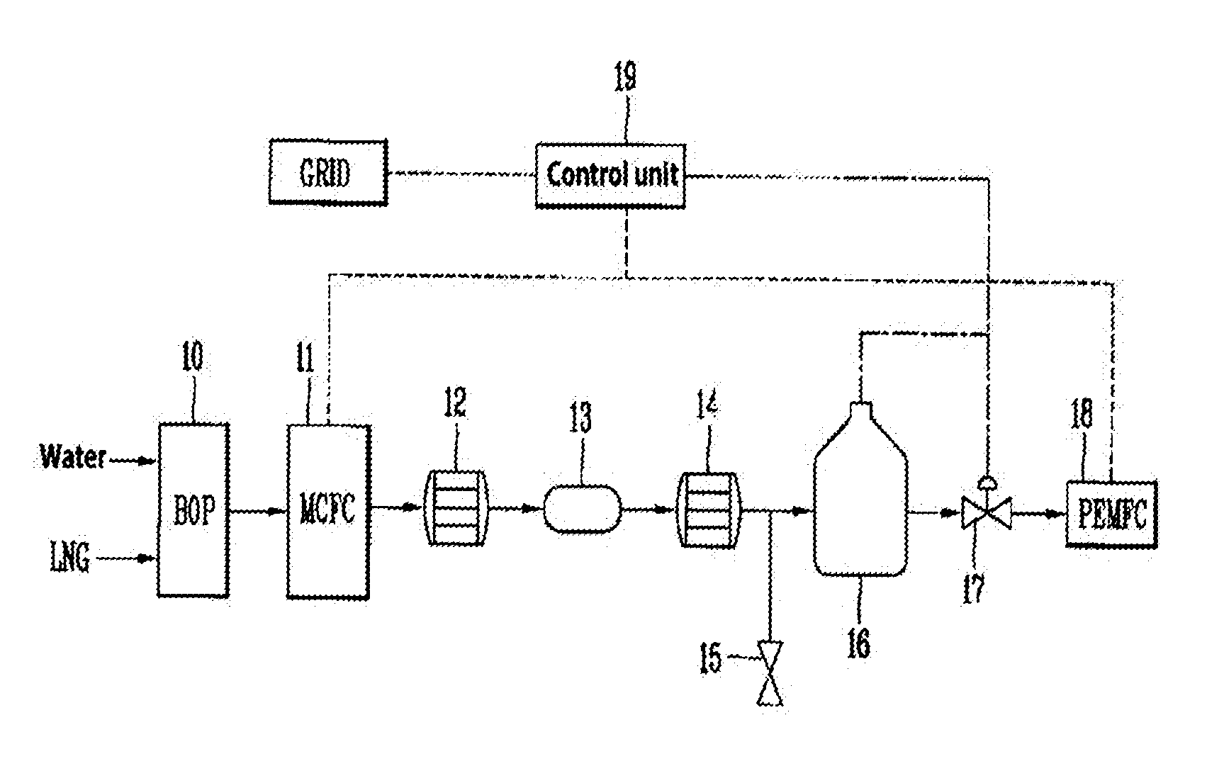
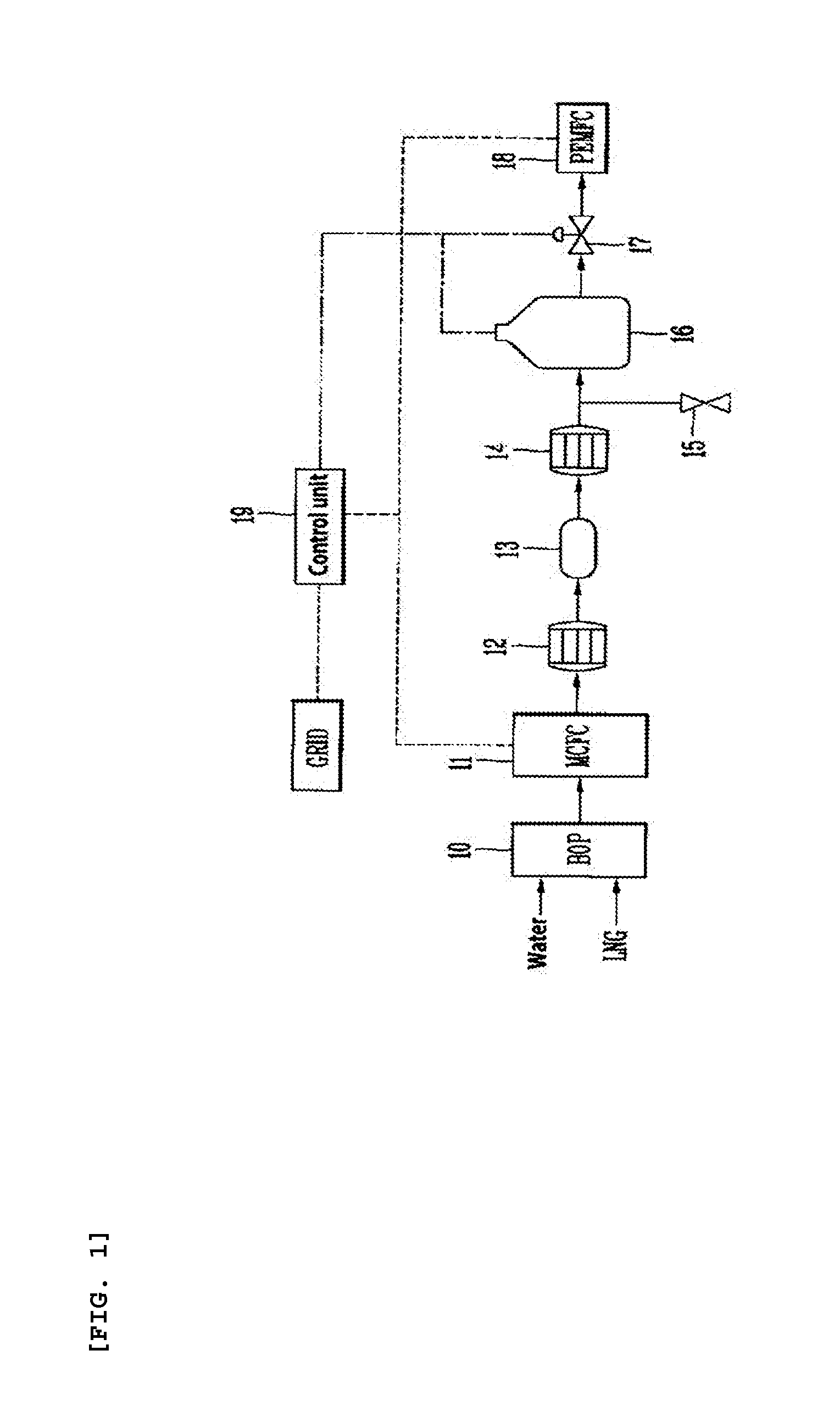
[0023]FIG. 1 is a diagram illustrating the configuration of a fuel cell system in accordance with the present invention.

[0024]As shown in FIG. 1, the fuel cell system in accordance with the first embodiment of the present invention includes a Molten Carbonate Fuel Cell (MCFC) 11; a Water Gas Shift (WGS) reactor 13 for shifting the discharge gas of the MCFC 11; a buffer tank 16 for storing hydrogen gas; and a Polymer Electrolyte Membrane Fuel Cell (PEMFC) 18 for being supplied with hydrogen gas from the buffer tank 16 (or various power generation devices driven using hydrogen gas).

[0025]The discharge gas of the MCFC 11 means the Anode Off Gas (AOG) of the MCFC 11 (e.g., gas discharged by the anode pole that belongs to the anode pole and cathode pole of the MCFC).

[0026]The AOG of the MCFC 11 may include some unreacted fuel (H2 and NG is the minimum) and other gases. The WGS reactor 13 removes some “CO”, included in the AOG that deteriorates the performance of the PEMFC 18, through a r...

second embodiment

[0054]FIG. 4 is a diagram illustrating the configuration of a fuel cell system in accordance with the present invention.

[0055]As shown in FIG. 4, the fuel cell system in accordance with the second embodiment of the present invention includes a Molten Carbonate Fuel Cell (MCFC) 11; first and second valves 21, 22 for selectively supplying the discharge gas of the MCFC 11; a valve control unit 20 for controlling the first and the second valves 21, 22; a Water Gas Shift (WGS) reactor 13 for shifting the discharge gas of the MCFC 11, supplied through the first valve 21, to water gas; a Polymer Electrolyte Membrane Fuel Cell (PEMFC) 18 for being supplied with hydrogen gas; and an oxidizer (or a catalyst burner) 24 for generating heat by oxidizing the discharge gas of the MCFC 11 supplied through the second valve 22.

[0056]The fuel cell system in accordance with the second embodiment of the present invention may further include a Balance Of Plant (BOP) 10, a first waste heat recovery unit 1...


PUM

PropertyMeasurementUnit
heataaaaaaaaaa
temperatureaaaaaaaaaa
electrical energyaaaaaaaaaa

Abstract

The present application relates to a fuel cell system and a method for driving same, which can produce stable electricity, enhance load following capability, and simultaneously increasing fuel utilization rate and energy efficiency by separately managing a base load and a load following of a fuel cell, and the fuel cell system according to one embodiment of the present application comprises: a molten carbonate fuel cell for generating electricity by using fuel; a reaction gas for shifting discharge gas into water gas; a buffer tank for storing the water gas; and a driving device which is actuated by using the water gas that is stored and provided from the buffer tank.

Description

TECHNICAL FIELD[0001]This specification relates to a fuel cell system and a method of driving the same.BACKGROUND ART[0002]In general, a fuel cell generates water and electricity using hydrogen and oxygen. The principle of operation of the fuel cell is that electrons are generated when hydrogen is ionized by the anode and the generated electrons move to the cathode through an electrolyte in the middle. Electrical energy is generated in a process of the electrons moving. A reaction in which water is generated by a reaction of hydrogen and air is an exothermic reaction, and heat and water can be obtained through such a reaction in addition to the electrical energy.[0003]In contrast, a reformed hydrogen compound is used as the fuel of a fuel cell because it is difficult to obtain hydrogen itself that is used as the fuel of a fuel cell. That is, fossil fuel, that is, a compound of carbon and hydrogen, is used as the fuel of a fuel cell.DISCLOSURETechnical Problem[0004]An object of this ...

Claims


Application Information

Patent Timeline
Patent Type & Authority Applications(United States)
IPC IPC(8): H01M8/06H01M8/04
CPCH01M8/0662H01M2008/1095H01M2008/147H01M8/04156H01M8/04014H01M8/04201H01M8/04604H01M8/04731H01M8/04738H01M8/04753H01M8/0494H01M8/0668H01M8/2495H01M2250/10Y02B90/10Y02E60/50H01M8/04H01M8/06H01M8/10H01M8/14
Inventor KIM, SUNG HOONYUN, CHOA MOONKIM, TAE HEELEE, GI PUNGLEE, TAE WON
Why Eureka
Try Eureka