Cooling Module for Electronic Engine Components

a technology of electronic engine components and cooling modules, which is applied in the direction of machines/engines, mechanical devices, volume/mass flow by differential pressure, etc., can solve the problems of limited emission, relatively high cost of solutions, and ineffectiveness of desired

Active Publication Date: 2014-12-04
CATERPILLAR INC
View PDF10 Cites 8 Cited by
  • Summary
  • Abstract
  • Description
  • Claims
  • Application Information

AI Technical Summary

Benefits of technology

[0005]In one aspect of the disclosure, a cooling module protects from overheating at least one electronic engine component situated proximally to the engine. The module, adapted to be secured to the exterior of an engine, includes a plurality of thermally conductive panels, and at least one panel includes an integral tubular coolant passage. The panels are joined together to form an enclosure defined by interior surfaces of the panels. The joined panels collectively define individual walls and a ceiling of the module to form a plurality of enclosing side walls and an enclosing ceiling. A floor and at least one side wall are substantially open to avoid the trapping of heat. The at least one component is substantially thermally shielded by the enclosing side walls and ceiling from engine generated heat.

Problems solved by technology

Such emissions are limited by federal laws and regulations in most countries.
The solution offered is relatively expensive, and may not be as effective as desired.

Method used


Image

  • Cooling Module for Electronic Engine Components
  • Cooling Module for Electronic Engine Components
  • Cooling Module for Electronic Engine Components

Examples


Embodiment Construction

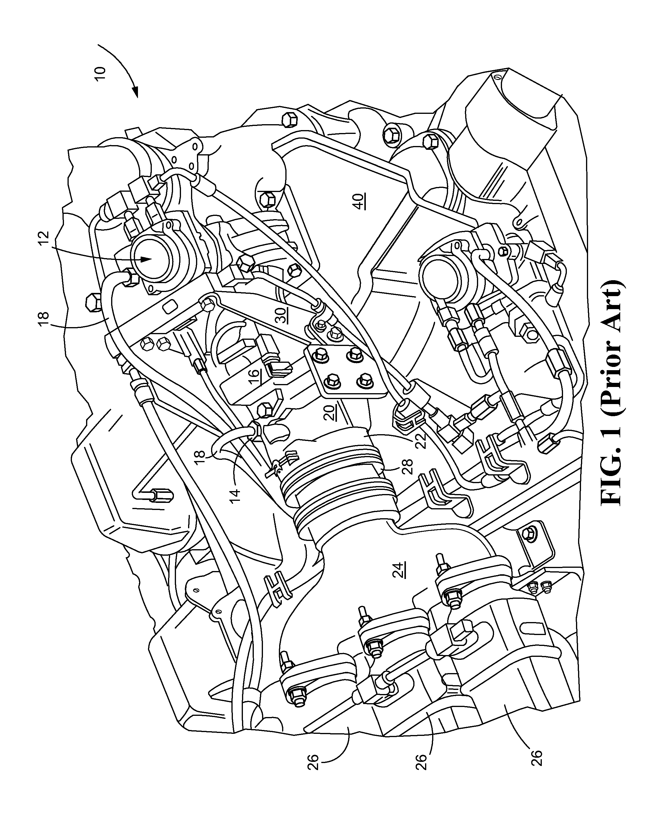
[0014]Referring initially to FIG. 1, an upper surface of an engine 10 includes an EGR valve 12, along with an absolute pressure sensor 14 and a differential or so-called Delta pressure sensor 16. Each of the sensors 14, 16 may have associated wiring and / or wiring harnesses 18. An EGR venturi 20 is generally associated with considerable heat output due to the high temperature exhaust gases flowing therethrough. The heat output of the EGR venturi 20 is known to be potentially deleterious to electronic components and associated wiring, including harnesses, attached thereto. A venturi inlet 22 may be adapted to receive high-pressure exhaust gases through a venturi header 24, also variously called a splitter, which may receive gases from a plurality of EGR coolers 26 (three are shown fragmentarily) situated upstream of the venturi 20.

[0015]A cooler-to-venturi coupling 28 assures airtight EGR gas flows into the venturi 20 from the coolers 26. A prior art bracket 30 has typically been empl...


PUM

PropertyMeasurementUnit
temperaturesaaaaaaaaaa
thermally conductiveaaaaaaaaaa
conductiveaaaaaaaaaa

Abstract

A multi-paneled cooling module adapted to be mounted to an engine exterior protects electronic components such as sensors and associated wiring from heat loads of the engine and / or other heat generating engine devices. The module is formed of wall and ceiling panels having a relatively high thermal conductivity, such as aluminum. The cooling module, which includes strategically situated integral coolant passages within several of its panels, is adapted to protect all enclosed electronic components, including electronic pressure sensors, an EGR valve, and all associated wiring and wiring harnesses. For example, the sensors, harnesses, and valve components associated with and proximal to an EGR venturi may be fully protected from overheating, in spite of exposure of those components to massive heat loads generated by the venturi. Finally, the cooling module may incorporate additional cooling accommodation for hydraulic oil cooling if, for example, the EGR valve is hydraulically actuated.

Description

TECHNICAL FIELD[0001]This disclosure relates generally to a system and method for protecting electronic components attached to engines subjected to deleteriously high temperatures and heat loads. More particularly, the disclosure relates to liquid cooled structural modules adapted to enshroud and shield such components from heat.BACKGROUND[0002]Exhaust emissions of internal combustion engines, particularly diesel engines, contain regulated exhaust constituents, mainly nitrogen oxides (NOX) and soot particles. Such emissions are limited by federal laws and regulations in most countries. One common way to reduce nitrogen oxide emissions is to use an exhaust gas recirculation (EGR) system wherein a part of the exhaust gas is purposely returned to the combustion chamber. This action leads to lower peak combustion temperatures, which in turn reduces formation of NOX.[0003]The typical modern diesel EGR system employs a so-called high pressure loop (HPL) system wherein a portion of engine ...

Claims


Application Information

Patent Timeline
Patent Type & Authority Applications(United States)
IPC IPC(8): F02B77/11B23P15/26
CPCB23P15/26F02B77/11F01P3/20F01P2050/30G01F1/44F02M2026/001Y10T29/49366F02M26/05F02M26/22F02M26/47
Inventor ROOZENBOOM, STEPHAN
Owner CATERPILLAR INC
Why Eureka
Try Eureka