Electric pump operating strategy

Active Publication Date: 2017-12-14
GM GLOBAL TECH OPERATIONS LLC
View PDF11 Cites 7 Cited by
  • Summary
  • Abstract
  • Description
  • Claims
  • Application Information

AI Technical Summary

Benefits of technology

[0013]It is a still further aspect of the present invention to provide a control method for a cooling system or circuit of an internal combusti

Problems solved by technology

Unfortunately, even the most sophisticated cooling system configurations are subject to variations caused by, for example, manufacturing and assembly variables and wear and aging of the components such as the pump impeller, the radiator and the hoses.
These variations cause variations in system backpressure which can result in flow reduction and temperature variations that deviate from design goals.
Today, an increasing number of internal combustion engines, obviously subject to today's performance expectations and requirements, utilize elec

Method used


Image

  • Electric pump operating strategy
  • Electric pump operating strategy
  • Electric pump operating strategy

Examples


Embodiment Construction

[0021]The following description is merely exemplary in nature and is not intended to limit the present disclosure, application, or uses.

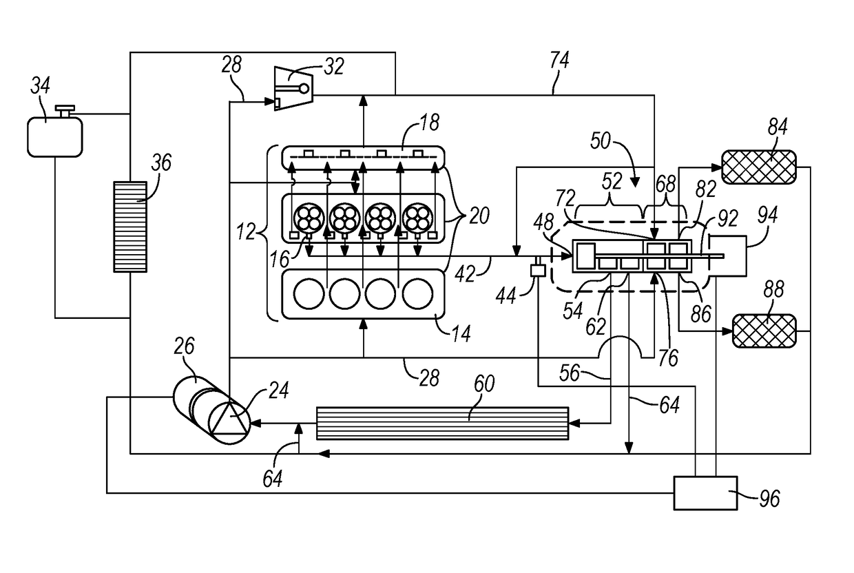
[0022]With reference to FIG. 1, an internal combustion engine and cooling system or circuit is illustrated and generally designated by the reference number 10. The engine and cooling system 10 includes an internal combustion engine 12 having an engine block 14 including cylinders and pistons, a head 16 including valves and an integrated exhaust manifold 18. These components of the internal combustion engine 12 are surrounded by a cooling jacket 20 through which a liquid coolant is circulated by an electric pump 24. The coolant pump 24 is driven by an electric motor 26. From the electric pump 24, the liquid coolant is circulated in a coolant supply line 28 to the components of the internal combustion engine 12, a turbocharger 32, a surge tank 34 and a heater core 36.

[0023]The coolant passing through the components of the internal combustion engine 12...


PUM


Abstract

A strategy for controlling an electric pump and control valve in an internal combustion engine cooling system compensates for backpressure variations and maintains system operation within design parameters. The method comprises the steps of measuring the coolant temperature, measuring the electrical current and voltage to the pump motor, determining the pump speed and coolant flow, determining the desired coolant flow, determining a negative correction to the flow control valve and pump if desired flow is less than present coolant flow and determining a positive correction to the flow control valve and pump if desired flow is more than present coolant flow and undertaking this correction to coolant flow. Thus, based upon inferred back pressure in the engine coolant system from the data relating to the pump energy input, proper coolant flow, heat rejection and engine operating temperature can be maintained in spite of variations in system flow restrictions and backpressure.

Description

FIELD[0001]The present disclosure relates to electric pumps utilized in internal combustion engine coolant circuits and more particularly to a strategy for controlling an electrically powered pump in an internal combustion engine coolant circuit.BACKGROUND[0002]The statements in this section merely provide background information related to the present disclosure and may or may not constitute prior art.[0003]The cooling circuit of an internal combustion engine and more particularly coolant flow in the cooling circuit of an internal combustion engine in a motor vehicle is critical not only from the fundamental standpoint of dissipating the heat of combustion to the ambient but also to accurately control the temperature of the engine to optimize performance and fuel economy.[0004]Significant engineering and design effort is directed to these operational parameters, especially the latter given increasingly stringent fuel economy requirements. Unfortunately, even the most sophisticated c...

Claims


Application Information

Patent Timeline
IPC IPC(8): F01P7/16
CPCF01P7/16F01P2007/146F01P7/164F01P2025/08
Inventor GONZE, EUGENE V.QUELHAS, SERGIORAMAPPAN, VIJAY A.PARATORE, JR., MICHAEL J.
Owner GM GLOBAL TECH OPERATIONS LLC
Why Eureka
Try Eureka