High efficiency solar power generator for offshore applications

a solar power generator and high-efficiency technology, applied in solar heat collectors for particular environments, photovoltaics, solar-ray concentration, etc., can solve the problems of expensive power supply to remote locations such as offshore platforms, costly transmission of electricity from land to offshore platforms, and difficult repairs

Active Publication Date: 2014-12-04
SAUDI ARABIAN OIL CO
View PDF6 Cites 1 Cited by
  • Summary
  • Abstract
  • Description
  • Claims
  • Application Information

AI Technical Summary

Benefits of technology

[0009]One aspect of the present invention relates to a dual-type solar power generator. The dual-type solar power generator includes a dual capture panel, where the dual capture panel includes a reflective surface, where the reflective surface is configured to reflect solar radiation having a reflecting wavelength to create a reflected stream and an absorbent surface, where the absorbent surface is configured to absorb solar radiation having an absorbent wavelength to create a released electron stream. The dual-type solar power generator also includes a thermal transfer unit. The thermal transfer unit includes a receiving zone being configured to receive the reflected stream and to absorb heat energy from the reflected stream, a heat engine, the heat engine being in thermal communication with the receiving zone, where the heat engine converts the heat energy absorbed by the receiving zone and converts the heat energy to mechanical work energy, and a generator, the generator in mechanical communication with the heat engine, where the generator is configured to convert the mechanical work energy to an electric current. The dual-type solar power generator includes an electric conditioning system, the electric conditioning system in electrical communication with the released electron stream and the electric current, the electric conditioning system includes an electrical buffer, the electrical buffer configured to prevent a cross flow of the released electron stream and the electric current, a dc-to-dc converter, the dc-to-dc converter configured to equalize a released electron stream voltage with an electric current voltage, and an electrical connector, the electrical connector configured to combine the released stream voltage with the electric current voltage to create a power source.
[0010]In certain embodiments, the dual capture panel has a parabolic shape with a focus point. In certain embodiments, the receiving zone is positioned at the focus point. In certain embodiments, the reflecting wavelength reflected by the reflective surface is greater than 1000 nm. In certain embodiments, the absorbent wavelength absorbed by the absorbent surface is less than 1000 nm. In certain embodiments, the absorbent surface includes a photovoltaic cell, where the photovoltaic cell is selected from the group consisting of mesh filter, interference filter, diffraction grating, and combinations thereof. In certain embodiments, the absorbent surface forms a layer contacting the reflective surface and positioned between the reflective surface and the thermal transfer unit. In certain embodiments, the receiving zone includes a fluid tank, wherein a fluid receives the heat energy to create heated fluid, the fluid tank being fluidly connected to the heat engine. in certain embodiments, the heat engine is a Stirling Engine. In certain embodiments, the electric buffer comprises a first diode in the released electron stream and a second diode in the electric current. In certain embodiments, the dual-type solar power generator includes a tracking system, the tracking system configured to orient the dual capture panel toward a source of the solar radiation. In certain embodiments, the dual-type solar power generator is operable to power a plurality of sensors. In certain embodiments, the dual-type solar power generator is used on an offshore platform.
[0011]A second aspect of the present invention relates to a method of generating dual-type solar power. The method includes the steps of capturing solar radiation with a dual capture panel, where the dual capture panel includes a reflecting surface and an absorbent surface, reflecting solar radiation having a reflecting wavelength with the reflecting surface to create a reflected stream, absorbing solar radiation having an absorbent wavelength with the absorbent surface to create a released electron stream, and converting a solar energy of the reflected stream to an electric current in a thermal transfer unit. The thermal transfer unit includes a receiving zone, a heat engine, and a generator. Converting the solar energy to an electric current in the thermal transfer unit includes the steps of heating a fluid in the receiving zone with the reflected stream to create a heated fluid having a heat energy, converting the heat energy of the heated fluid to mechanical work energy in the heat engine, the heat engine being fluidly connected to the receiving zone, and converting the mechanical work energy to the electric current in it generator, the generator being mechanically connected to the heat engine. The method further includes combining the electric current and the released electron stream in an electric conditioning system. The electric conditioning system includes an electrical buffer configured to prevent a cross flow of the released electron stream and the electric current, a dc-to-dc converter, the dc-to-dc converter configured to equalize a released electron stream voltage with an electric current voltage, and an electrical connector, the electrical connector configured to combine the released stream voltage with the electric current voltage to create a power supply.

Problems solved by technology

Supplying power to remote locations, such as an offshore platform, is costly.
White possible, transmitting electricity from land to an offshore platform is costly because of the capital required to transmit electricity over long distances.
Additionally, due to the remote nature of the transmission lines themselves, repairs are difficult.
Onsite methods of power generation are generally not a better option due to the need to minimize the footprint of the equipment, the footprint being the area measured on the ground that the equipment requires.
A smaller footprint often means reduced electricity capability.
Electricity generation on this scale requires a large footprint for the mirror array.
In addition, photovoltaic cells have relatively low efficiency.

Method used


Image

  • High efficiency solar power generator for offshore applications
  • High efficiency solar power generator for offshore applications
  • High efficiency solar power generator for offshore applications

Examples


Embodiment Construction

[0015]While the invention will be described with several embodiments, it is understood that one of ordinary skill in the relevant art will appreciate that many examples, variations and alterations to the apparatus and methods described herein are within the scope and spirit of the invention. Accordingly, the exemplary embodiments of the invention described herein are set forth without any loss of generality, and without imposing limitations, on the claimed invention.

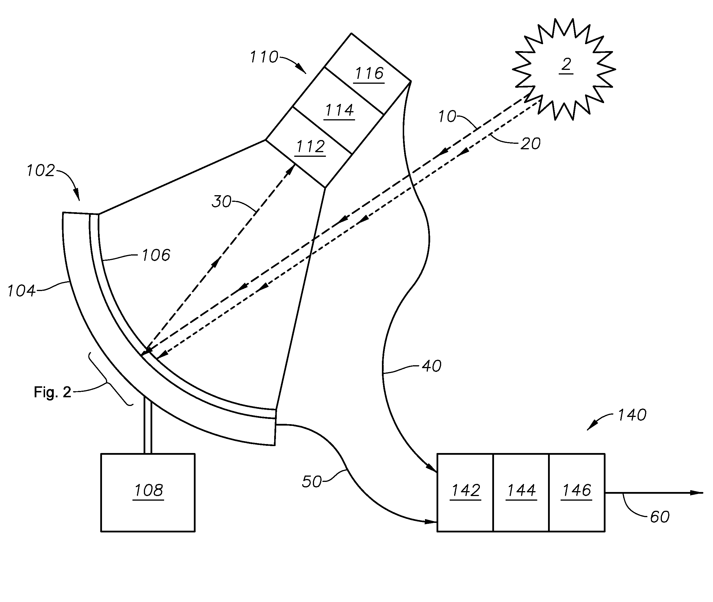
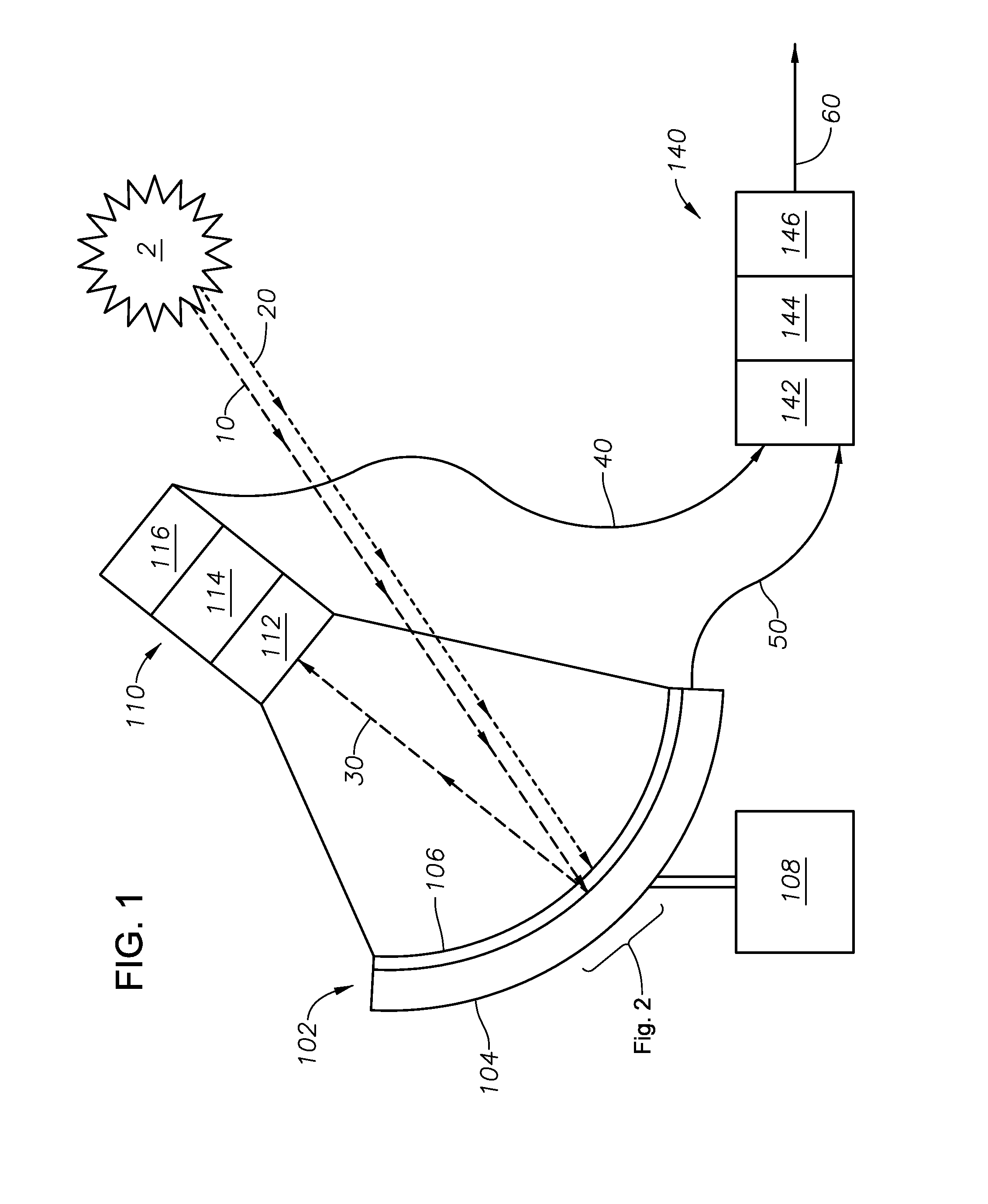
[0016]FIG. 1 provides a schematic of an embodiment of the present invention. Dual-type solar power generator 100 includes dual capture panel 102. Dual capture panel 102 is designed to reflect reflecting wavelengths of solar radiation and to absorb absorbent wavelengths of solar radiation from solar radiation source 2. In a preferred embodiment, dual capture panel 102 has a parabolic shape. In an alternate embodiment, dual capture panel 102 includes one or more flat panels (not shown) arranged in a parabolic shape. Dual c...


PUM


Abstract

A dual-type solar power generator comprising a dual capture panel. The dual capture panel comprises a reflective surface configured to reflect solar radiation having a reflecting wavelength and an absorbent surface configured to absorb solar radiation having an absorbent wavelength to create a released electron stream. A thermal transfer unit comprising a receiving zone configured to absorb heat energy, a heat engine that converts the heat energy to mechanical work energy, and a generator configured to convert the mechanical work energy to an electric current, an electric conditioning system comprising an electrical buffer configured to prevent a cross flow of the released electron stream and the electric current, a power converter configured to equalize a released electron stream voltage with an electric current voltage, an electrical connector configured to combine the released stream voltage with the electric current voltage to create a power source.

Description

FIELD OF THE INVENTION[0001]This invention relates to a system and process for dual-type solar power generation. Specifically, the present invention relates to a dual capture panel using both photovoltaics and a concentrating solar power system to generate electricity.BACKGROUND OF THE INVENTION[0002]Supplying power to remote locations, such as an offshore platform, is costly. White possible, transmitting electricity from land to an offshore platform is costly because of the capital required to transmit electricity over long distances. Transmission to offshore platforms requires new transmission lines and other equipment. Additionally, due to the remote nature of the transmission lines themselves, repairs are difficult. Onsite methods of power generation are generally not a better option due to the need to minimize the footprint of the equipment, the footprint being the area measured on the ground that the equipment requires. A smaller footprint often means reduced electricity capab...

Claims


Application Information

Patent Timeline
Patent Type & Authority Applications(United States)
IPC IPC(8): H02J1/10F24S20/20
CPCH02J1/10F03G6/001F03G6/068F24S20/20F24S23/71F24S23/82H02S10/00H02S20/32Y02E10/46Y02E10/52F03G6/062Y02E10/40
Inventor BLACK, MICHAEL JOHNSAEED, ABUBAKER
Owner SAUDI ARABIAN OIL CO
Why Eureka
Try Eureka