System and method for safe, wireless energy transmission

a wireless energy transmission and wireless technology, applied in electromagnetic wave systems, transformers, inductances, etc., can solve the problems of inability to accurately aim the energy beam, inability to achieve the desired effect,

Inactive Publication Date: 2014-12-04
ESCAPE DYNAMICS
View PDF0 Cites 45 Cited by
  • Summary
  • Abstract
  • Description
  • Claims
  • Application Information

AI Technical Summary

Problems solved by technology

Unfortunately, a number of challenges have also been identified in regard to wireless energy transmission.
The requirement for precision in aiming the energy beam can be particularly challenging in the presence of environmental factors such as wind and vibration.
Other problems include the inherent production of energy transmission lobes along sides of a transmitting antenna.
Such side lobes may be undesirable for a number of reasons including safety and interference with other transmissions.
To date, however, practical, safe, scalable and affordable operation of wirelessly powered aerial vehicles has not been achieved.

Method used


Image

  • System and method for safe, wireless energy transmission
  • System and method for safe, wireless energy transmission
  • System and method for safe, wireless energy transmission

Examples


Embodiment Construction

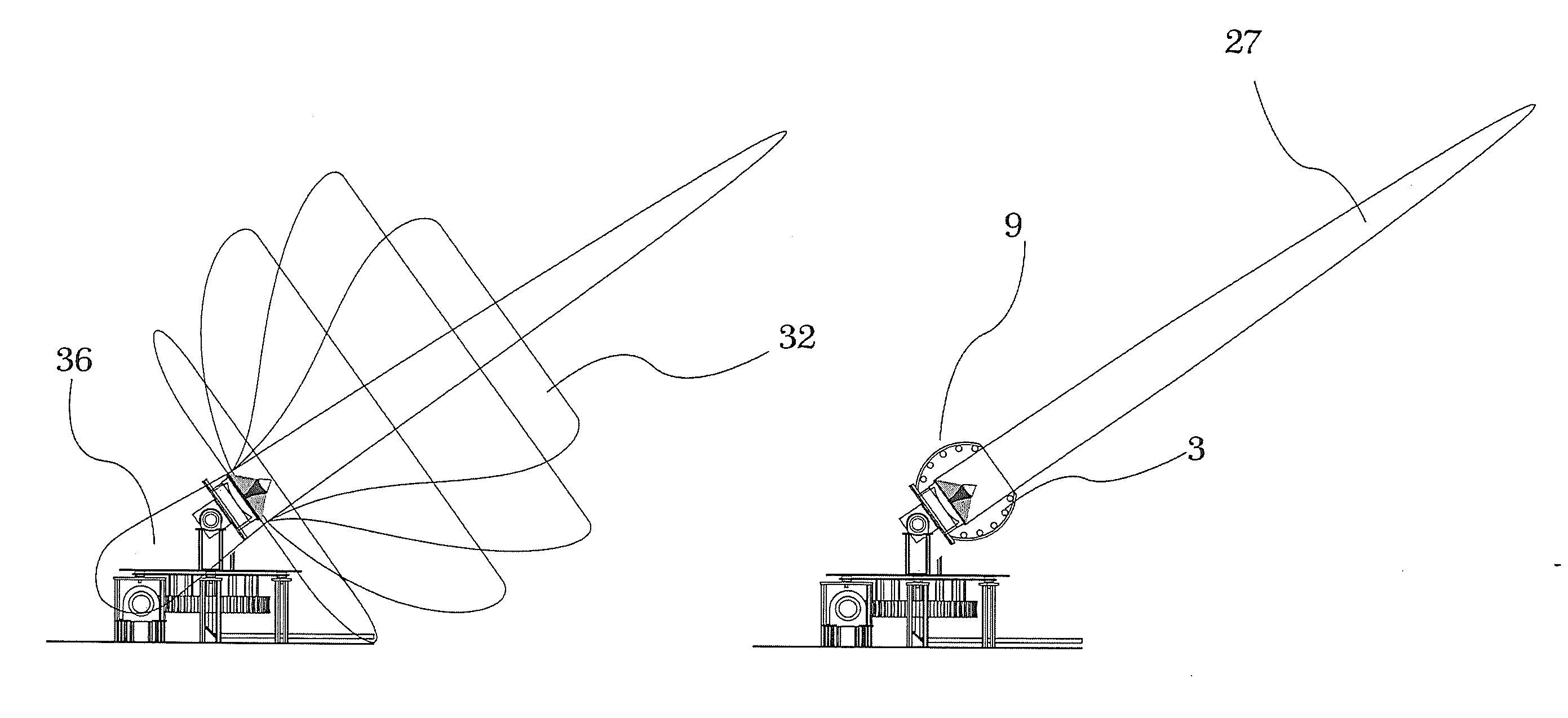
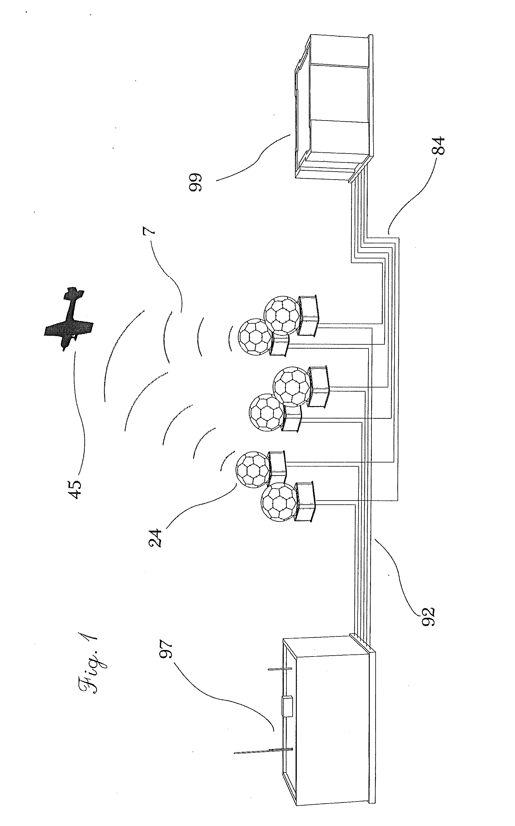
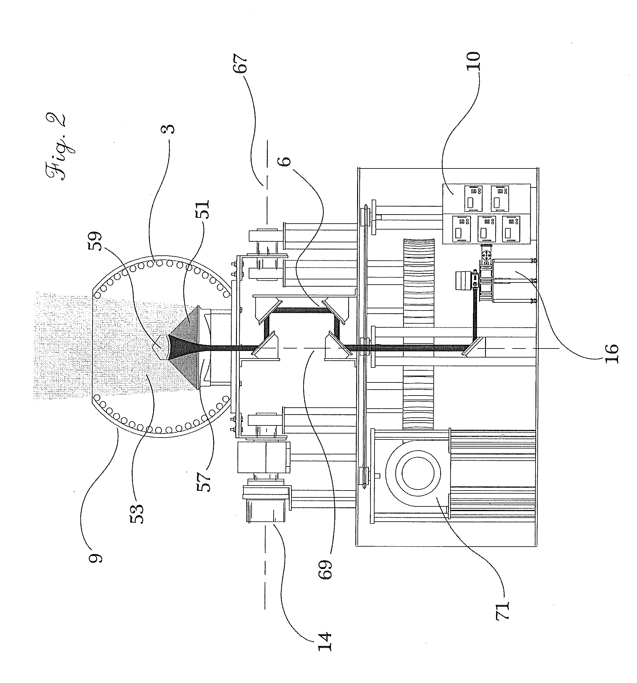
[0019]In an exemplary embodiment, a system for transmitting energy comprises a controller operably coupled to a plurality of energy transmitters. Each energy transmitter comprises a microwave generator coupled to a source of electrical energy. The microwave generator is configured for receiving electrical energy from the source of electrical energy and emitting a beam of electromagnetic energy. In one exemplary embodiment, energy from electric grid is received by a gyrotron, and a beam of millimeter waves is emitted from the gyrotron.

[0020]Electricity from the electric grid may be received in a form of 3 phase AC current at fixed nominal voltage (e.g., 480V) and may be converted through a dedicated power supply source into a high voltage DC current before entering the microwave generator, which may comprise a gyrotron. In another exemplary embodiment, the source of energy is an electrical generator which provides either AC or DC electric current to the microwave generator. It should...


PUM


Abstract

A system for transmitting energy comprises a controller operably coupled to a plurality of energy transmitters. Each of the transmitters comprises a microwave generator, a waveguide positioned for receiving the beam of electromagnetic energy from the microwave generator, an antenna positioned for receiving the guided beam of electromagnetic energy, and a radome disposed about the antenna. The microwave generator is configured for emitting a beam of electromagnetic energy. The waveguide is configured for receiving the beam of electromagnetic energy and emitting a guided beam of electromagnetic energy. The antenna is configured for forming a directional beam of microwave energy with a controlled phase, and the directional beam of microwave energy has controlled energy distribution properties. The controller is configured for modulating at least one attribute of the directional beam of microwave energy of each energy transmitter of the plurality of energy transmitters.

Description

CROSS-REFERENCE TO RELATED APPLICATIONS[0001]This patent application claims priority to U.S. Provisional Patent Application Ser. No. 61 / 828,496 filed May 29, 2013, which is incorporated herein by reference in its entirety.BACKGROUND OF THE INVENTION[0002]The present invention relates to systems and methods for wirelessly transmitting energy and more particularly to an improved system and method for wirelessly transmitting energy including a microwave generator, a waveguide, an antenna, and a radome disposed about an antenna.[0003]The utility of wireless transmission of electromagnetic energy has been recognized for many potential applications including providing a source of power to remotely located objects such as an aerial vehicle. Unfortunately, a number of challenges have also been identified in regard to wireless energy transmission. For example, the magnitude of energy to be transmitted in many currently envisioned applications tends to exacerbate the importance of safety, rel...

Claims


Application Information

Patent Timeline
Patent Type & Authority Applications(United States)
IPC IPC(8): H02J17/00
CPCH02J17/00H01Q1/02H01Q1/3216H01Q1/42H01Q3/08H01Q3/32H01Q15/0013H01Q17/001H01Q19/191H02J50/20H02J50/90H02J50/80H02J50/60H02J50/005H02J50/40
Inventor TSELIAKHOVICH, DMITRIY
Owner ESCAPE DYNAMICS
Why Eureka
Try Eureka