Dairy farm fluid line treatment

Inactive Publication Date: 2014-12-04
2178450 ONTARIO
View PDF1 Cites 4 Cited by
  • Summary
  • Abstract
  • Description
  • Claims
  • Application Information

AI Technical Summary

Benefits of technology

[0013]The invention relates to drawing ozone gas into a fluid line of a dairy farm milking system in order to provide antibacterial treatment of fluid passing through the fluid line so as to kill air borne bacteria before it is drawn

Problems solved by technology

However, due to the respective locations at which each of the air and liquid sections enter the receiver jar, liquid in the liquid section generally cannot enter into the air section.
However, the floor on which the animal is standing is typically at least somewhat soiled with the animal's fecal matter and urine which can, along with the surrounding air, contain high levels of bacteria.
High levels of bacteria within milk present health risks to those who will consume the milk and the milk products derived from the milk such as cre

Method used


Image

  • Dairy farm fluid line treatment
  • Dairy farm fluid line treatment
  • Dairy farm fluid line treatment

Examples


Example

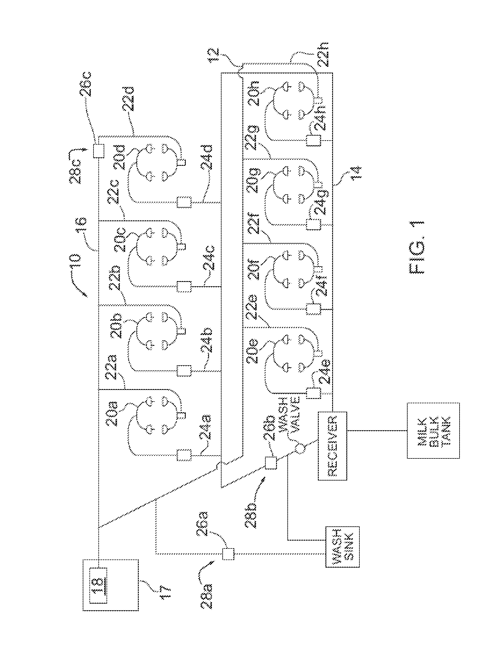
[0022]Turning now to FIG. 1, there is shown a dairy farm milking system 10 with integrated fluid line treatment components, according to an embodiment. The dairy farm milking system 10 includes a fluid line 12 having a liquid section 14 and an air section 16, and a vacuum subsystem 17 including a vacuum pump 18 in fluid communication with the fluid line 12 for imparting a vacuum within the fluid line 12. In this embodiment, the vacuum pressure is about 11 to about 16 pounds per square inch (PSI). Eight milking units 20a, 20b, 20c, 20d, 20e, 20f, 20g, 20h are in fluid communication with the fluid line 12. The milking units 20a-h each include an air tube 22a-h coupled to the air section 16 of the fluid line 12, and a milk tube 24a-h coupled to the liquid section 14 of the fluid line 12 for introducing harvested milk to the fluid line 12.

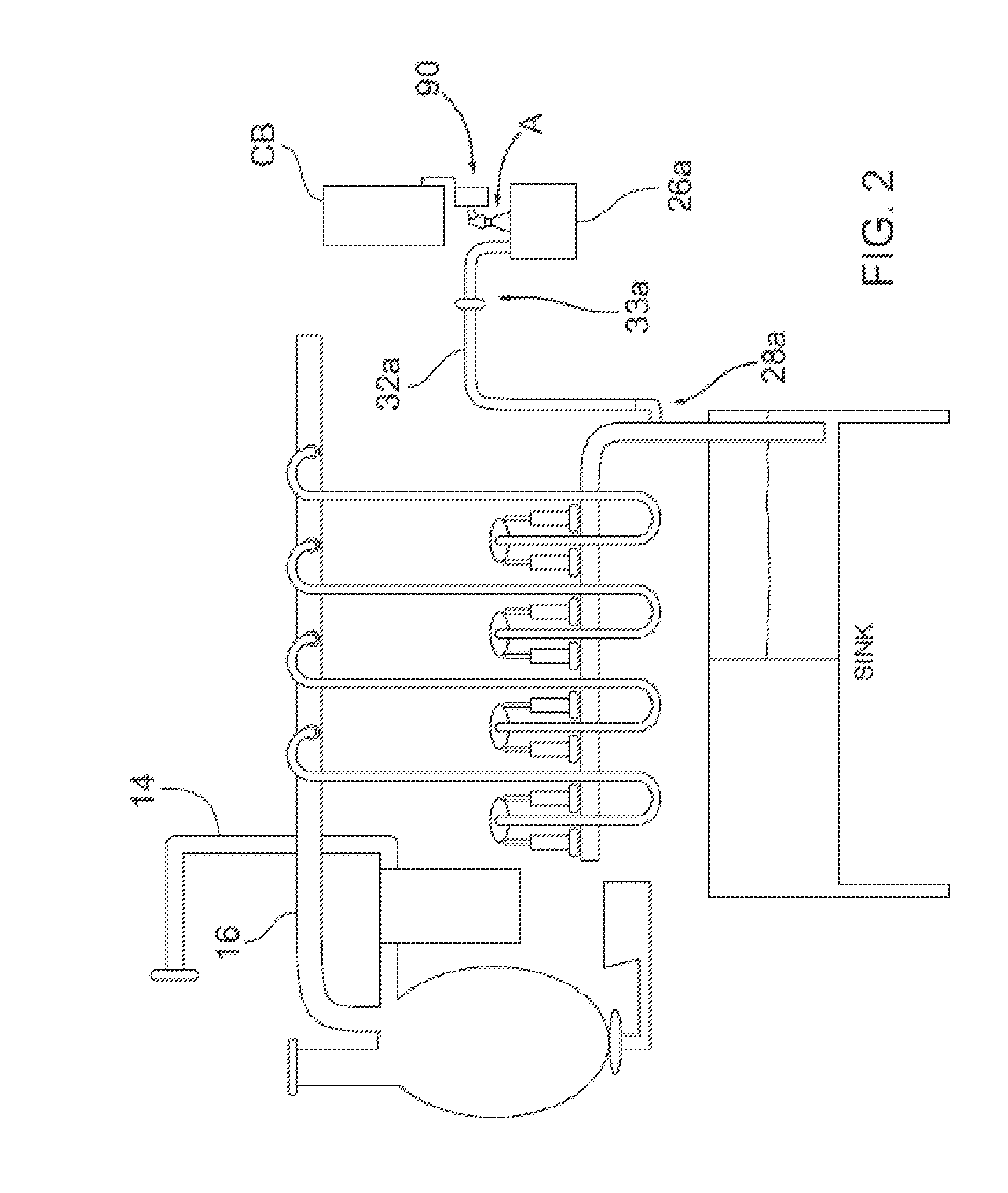
[0023]In this embodiment, the fluid line treatment kit components include three ozone gas sources 26a, 26b and 26c configured to provide ozone gas to ...


PUM


Abstract

A fluid line treatment kit for a dairy farm milking system having a vacuum subsystem for imparting vacuum within a fluid line is provided. The fluid line treatment kit includes at least one ozone gas source; a conduit associated with each ozone gas source configured to convey ozone gas to within the fluid line at a respective location; and a control system configured to trigger each ozone gas source to produce ozone gas while the vacuum subsystem is actuated. Vacuum imparted by the vacuum subsystem in the fluid line draws ozone gas via the at least one conduit into and through the fluid line.

Description

CROSS REFERENCE TO RELATED APPLICATION[0001]This application claims priority under 35 U.S.C. 119(e) from U.S. Provisional Patent Application Ser. No. 61 / 830,347 filed on Jun. 3, 2014.FIELD OF THE INVENTION[0002]The present invention relates generally to dairy farm milking systems, and more particularly to treating fluid such as air passing through a fluid line of a dairy farm milking system using ozone gas.BACKGROUND OF THE INVENTION[0003]A dairy farm milking system is for harvesting milk from animals such as cows and goats. Such a system is typically installed within a barn or other building, and is configured to extract, convey and temporarily store the milk being harvested from the animals.[0004]Various dairy farm milking systems are known. For example, a milking parlour typically refers to a system in which each animal enters a milking station for extraction of their milk, whereas a milking stall system is one in which each animal is positioned in a respective stall and the prod...

Claims


Application Information

Patent Timeline
IPC IPC(8): A61L2/20A01J5/00A01J7/02
CPCA61L2/202A01J5/00A01J7/02
Inventor MCLEAN, BRIANSTRAIN, PETER
Owner 2178450 ONTARIO
Why Eureka
Try Eureka