
Continuous production of carbon nanomaterials using a high temperature inductively coupled plasma

a technology of inductively coupled plasma and carbon nanomaterials, which is applied in the direction of physical/chemical process catalysts, other chemical processes, separation processes, etc., can solve the problems of inhibiting free flow, and achieve the effects of increasing energy density, significant efficiency, and enhancing product valu

Inactive Publication Date: 2010-02-23
SEQUOYAH FINANCE ONE
View PDF12 Cites 4 Cited by
  • Summary
  • Abstract
  • Description
  • Claims
  • Application Information

AI Technical Summary

Benefits of technology

"The present invention is about an economical method for producing carbon nanomaterials (CNMs) in flight, at high production rates, by continuously injecting carbonaceous and catalytic materials into a plasma field produced by an ICP torch. The method involves controlling reactor chamber conditions to provide a suitable environment for the formation and growth of CNMs. The CNMs can be integrated into various products to enhance their energy density, improve their structural, electrical conductivity, and thermal conductivity properties. The method is carried out in a high-temperature gas phase environment, which allows for continuous vaporization and mixture of precursors for CNM formation and in-flight growth of CNMs. The gas stream can be filtered to selectively recover the CNMs and the catalyst, which can be reused. The CNMs can also be integrated into a product to enhance its value."

Problems solved by technology

Such baffles would likely inhibit the free flow that is desired to optimize the in-flight production of CNMs.

Method used


Image

  • Continuous production of carbon nanomaterials using a high temperature inductively coupled plasma
  • Continuous production of carbon nanomaterials using a high temperature inductively coupled plasma
  • Continuous production of carbon nanomaterials using a high temperature inductively coupled plasma

Examples


Embodiment Construction

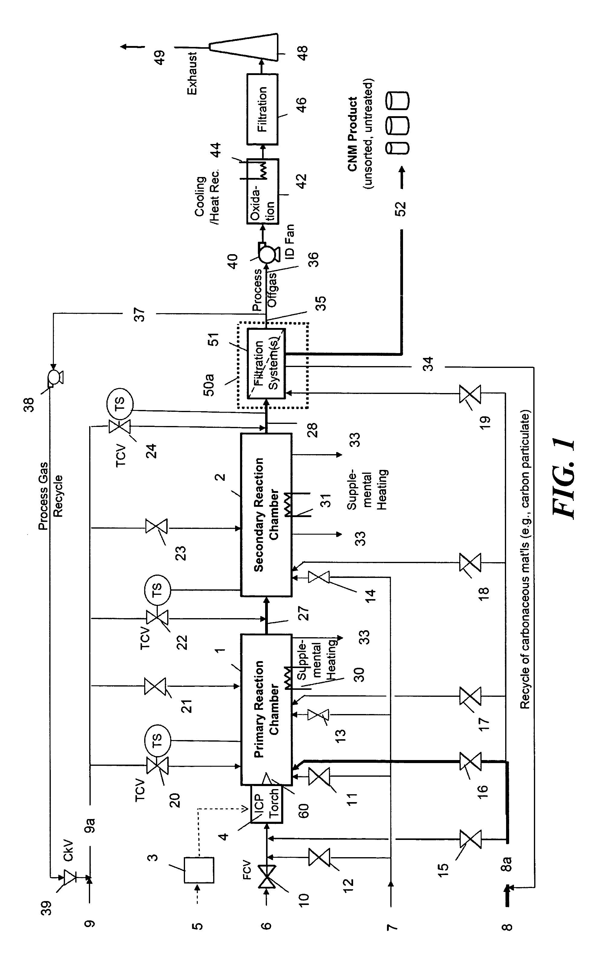
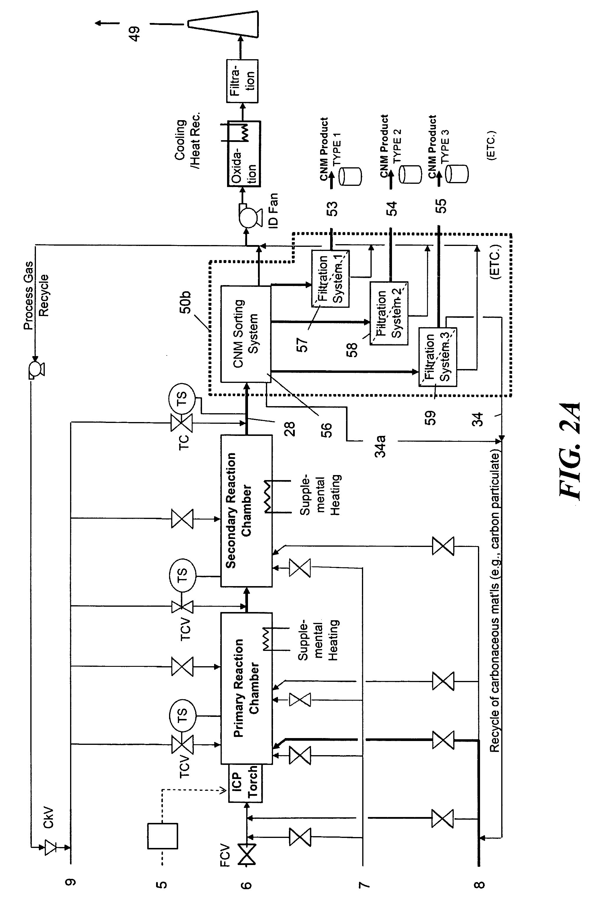
[0042]A method discussed below is used to produce CNMs in a gas phase reaction using the high temperature gas emitted from an ICP torch to crack carbonaceous materials in a flowing gas stream, where the carbon is mixed with suitable catalytic materials in the presence of other gaseous elements that promote the formation of the CNMs. This method offers flexibility in the production of various CNMs, including but not limited to graphitic SWCNTs, graphitic MWCNTs, graphitic carbon nanofibers, and amorphous carbon nanowires.

[0043]The continuously operated and controlled gas-phase reaction process uses a high-power ICP torch as the main source of heat for continuous thermal cracking of carbonaceous materials to provide free carbon, and for heating nano-scale metal-based catalysts (the generation of nano scale catalyst particles is discussed in greater detail below). The heated carbon and catalyst serve as precursors for the formation of CNMs downstream of the ICP torch. An initial nano-s...


PUM

PropertyMeasurementUnit
temperatureaaaaaaaaaa
particle sizeaaaaaaaaaa
temperaturesaaaaaaaaaa

Abstract

High-power inductively coupled plasma technology is used for thermal cracking and vaporization of continuously fed carbonaceous materials into elemental carbon, for reaction with separate and continuously fed metal catalysts inside a gas-phase high-temperature reactor system operating at or slightly below atmospheric pressures. In one particularly preferred embodiment, in-flight growth of carbon nanomaterials is initiated, continued, and controlled at high flow rates, enabling continuous collection and product removal via gas / solid filtration and separation methods, and / or liquid spray filtration and solid collection methods suitable for producing industrial-scale production quantities. In another embodiment, the reaction chamber and / or filtration / separation media include non-catalytic or catalytic metals to simultaneously or separately induce on-substrate synthesis and growth of carbon nanomaterials. The on-substrate grown carbon nanomaterials are produced in secondary chambers that are selectively isolated for periodic removal of the product.

Description

RELATED APPLICATIONS[0001]This application is based on prior provisional application Ser. No. 60 / 477,710, filed on Jun. 10, 2003, the benefit of the filing date of which is hereby claimed under 35 U.S.C. §119(e).FIELD OF THE INVENTION[0002]The present invention relates to method and apparatus for utilizing an inductively coupled plasma torch to produce carbon nanomaterials, and more specifically, relates to a method and apparatus for producing graphitic single-wall carbon nanotubes, graphitic multi-walled carbon nanotubes, graphitic carbon nanofibers, and amorphous carbon nanowires in a continuous-flow, in-flight production process.BACKGROUND OF THE INVENTION[0003]Carbon nanotubes are seamless tubes of graphite sheets with complete fullerene caps and were first discovered as multi-layer concentric tubes or multi-walled carbon nanotubes, and subsequently, as single-wall carbon nanotubes. Nanotubes are typically formed in the presence of transition metal catalysts. Carbon nanotubes ha...

Claims


Application Information

Patent Timeline
Patent Type & Authority Patents(United States)
IPC IPC(8): D01F9/12B82B3/00B82B1/00C01BC01B31/00C01B31/02
CPCB01J19/088B82Y30/00B82Y40/00C01B31/02C01B31/0233D01F9/12Y10S977/844B01J2219/0869B01J2219/0871B01J2219/0886B01J2219/0892B01J2219/0894C01B2202/02C01B2202/06B01J2219/0807C01B32/05C01B32/162
Inventor HENDERSON, MARKVAVRUSKA, JOHNBLUTKE, ANDREASFERGUSON, ROBERT
Owner SEQUOYAH FINANCE ONE
Learn More