Centrifugal Air Cycle Air Conditioner

a centrifugal air cycle and air conditioner technology, which is applied in the field of centrifugal air cycle air conditioners, can solve the problems of thinning of the boundary layer and maximizing the heat transfer in the heat exchanger

Inactive Publication Date: 2013-01-03
LEVY GEORGE SAMUEL
View PDF1 Cites 4 Cited by
  • Summary
  • Abstract
  • Description
  • Claims
  • Application Information

AI Technical Summary

Benefits of technology

[0058]FIG. 10 provides a top view of a centrifuge variation that utilizes the Coriolis Effect to force the air movement inside the heat exchanger.
[0059]FIG. 11 is a cross-sectional view of the centrifuge variation that utilizes the Coriolis Effect to force the air movement inside the heat exchanger.
[0060]FIG. 12 is an exploded view of the centrifuge variation that utilizes the Coriolis Effect to force the air movement inside the heat exchanger.
[0061]FIG. 13 is an exploded view of the heat exchanger variation that utilizes the Coriolis Effect to force the air movement inside the heat exchanger.
[0062]FIG. 14 provides one possible embodiment for the heat exchanger variation that utilizes the Coriolis Effect to force the air movement inside the heat exchanger. This variation utilizes annular heat dissipation fins and annular guide fins.

Problems solved by technology

This rapid motion of the air results in the thinning of the boundary layer and in the maximization of heat transfer in the heat exchanger.

Method used


Image

  • Centrifugal Air Cycle Air Conditioner
  • Centrifugal Air Cycle Air Conditioner
  • Centrifugal Air Cycle Air Conditioner

Examples


Embodiment Construction

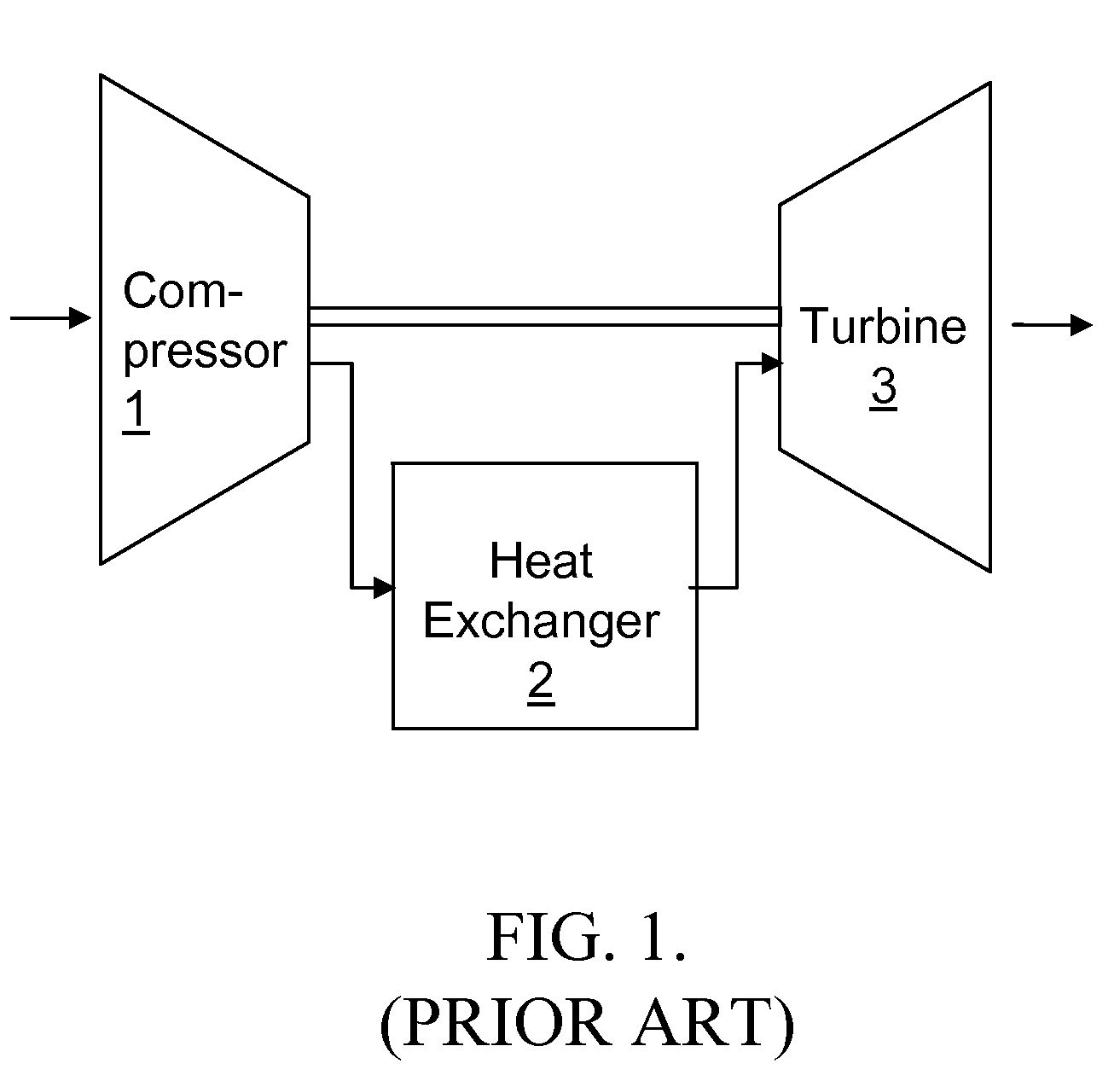
[0069]The device operates according to a reverse Brayton cycle also called an air refrigeration cycle or a Bell Coleman cycle shown in the prior art FIG. 1. In this well know cycle, the air is compressed adiabatically in a compressor 1. The air then traverses a heat exchanger 2 where it is cooled essentially at constant pressure. The air is then adiabatically decompressed and cooled in a turbine 3.

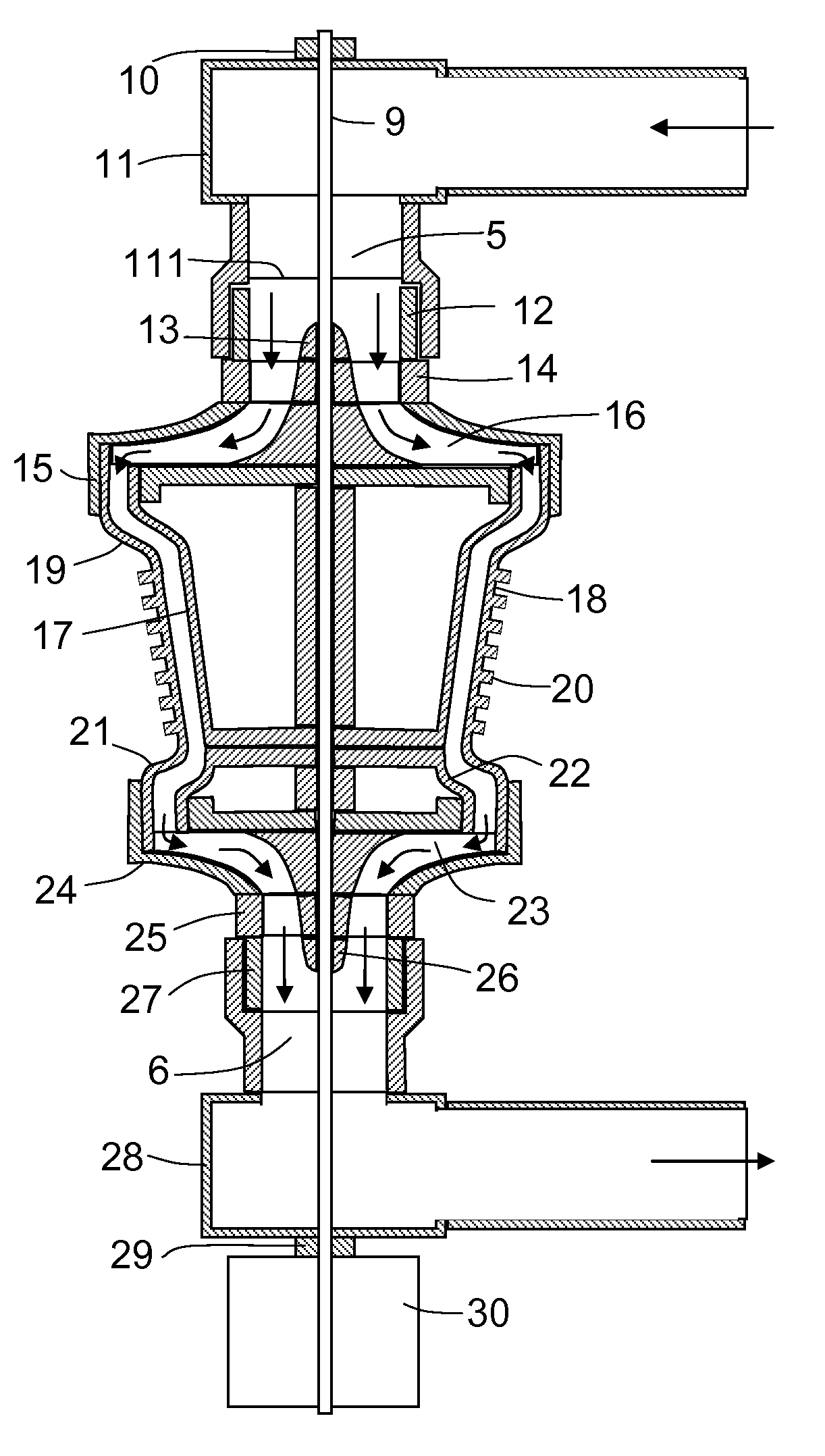
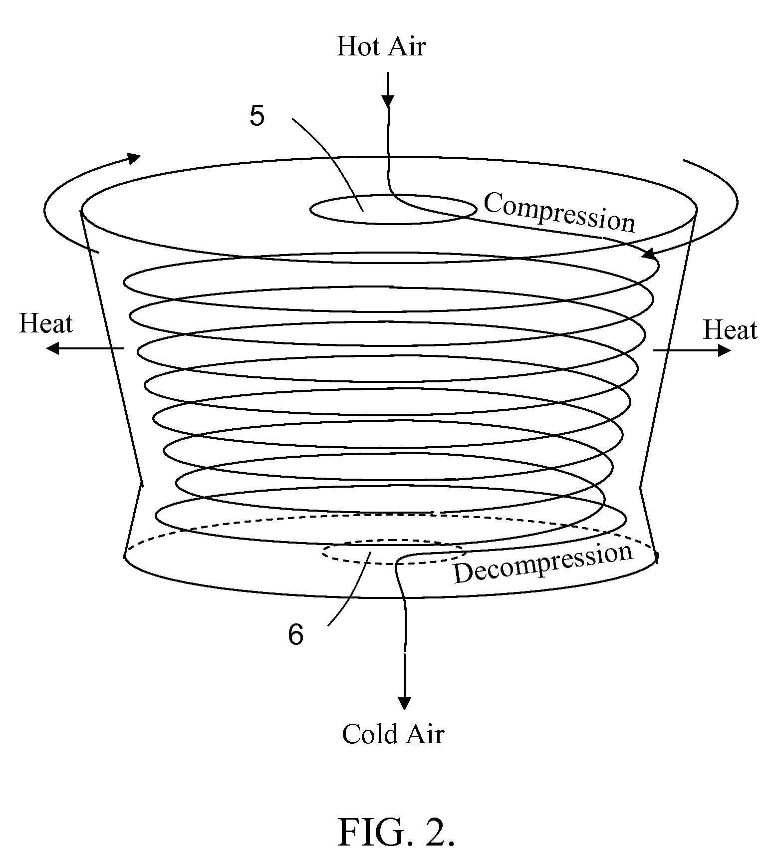
[0070]The proposed air conditioner implements the reverse Brayton cycle by means of a centrifuge driven by an electric motor as shown in diagrammatical form in FIG. 2, and in fully assembled form in FIG. 3. All the parts in the figure rotate as a unit. FIG. 4 includes inlets and outlets and FIG. 5 shows the device in cross-section.

[0071]This architecture allows the device to operate simultaneously as a compressor, heat exchanger and turbine. Hot outdoor air enters the device through an axial inlet 5. The air, propelled by a first set of impellers 16, acquires rotational kinetic energy, is ...


PUM


Abstract

The air conditioning system uses an air cycle thermodynamic process. The system comprises a centrifuge. This centrifuge includes at one of its ends, an axial inlet that funnels air into a centrifugal compressor rotating in unison with the centrifuge. The air is compressed, adiabatically heated and directed to a heat exchanger mounted in the rim of, and rotating with the centrifuge. The air is accelerated with respect the centrifuge by varying the centrifuge radius or by using forward leaning impeller blades. The air is cooled by the heat exchanger and directed to an expander also rotating with the centrifuge. The air is expanded and adiabatically further cooled. The cold air exits the centrifuge through an axial outlet located at the second end of the centrifuge.

Description

[0001]This invention claims the priority benefit of U.S. provisional application No. 61 / 235,230 titled “Air Cycle Air-Conditioning Fan” filed on Aug. 19, 2009, and of U.S. Provisional Application No. 61 / 254,717 titled “Air Cycle Air-Conditioner” filed on Oct. 25, 2009, both of which are hereby incorporated by reference. Applicant claims priority pursuant to 35 U.S.C. Par 119(e)(i).[0002]This invention is a continuation in part of application U.S. application with application Ser. No. 12,856,652 by Levy and titled “Centrifugal Air Cycle Air Conditioner” filed on Aug. 14, 2010, which is hereby incorporated by reference and which is to be abandoned.[0003]This invention also claims the priority benefit of U.S. provisional application No. 61 / 533,067 titled “Centrifugal Air Cycle Air Conditioner” filed on Sep. 09, 2011 which is hereby incorporated by reference. Applicant claims priority pursuant to 35 U.S.C. Par 119(e)(i).FIELD OF THE INVENTION[0004]The present invention relates to air co...

Claims


Application Information

Patent Timeline
Patent Type & Authority Applications(United States)
IPC IPC(8): F25B9/06
CPCF25B9/004
Inventor LEVY, GEORGE SAMUEL
Owner LEVY GEORGE SAMUEL
Why Eureka
Try Eureka