Power oscillation damping by a converter-based power generation device

a power generation device and converter technology, applied in the direction of electric generator control, dynamo-electric converter control, machines/engines, etc., to achieve the effect of minimizing any power loss

Active Publication Date: 2014-12-11
SIEMENS GAMESA RENEWABLE ENERGY AS
View PDF13 Cites 12 Cited by
  • Summary
  • Abstract
  • Description
  • Claims
  • Application Information

AI Technical Summary

Benefits of technology

[0017]According to an embodiment of the herein disclosed subject matter, the controller comprises first subcontroller for controlling an active component of the electrical output power and a second subcontroller for controlling a reactive component of the electrical output power. Two parallel controllers, of which one is provided for controlling the active component and the other is provided for controlling the reactive component of the electrical output power, have the advantage that the control of the active component and the reactive component can be performed independently. However, it should be understood that any control is possible only within the various limits of the components of the power generation device.
[0018]However, some power generation devices in accordance with embodiments of the herein disclosed subject-matter operate with an energy source free of charge, for example wind or solar energy. At least in such a

Problems solved by technology

However, if there is insufficient damping in the power system for this particular oscillation an ever increasing amount of active power is exchang

Method used


Image

  • Power oscillation damping by a converter-based power generation device
  • Power oscillation damping by a converter-based power generation device
  • Power oscillation damping by a converter-based power generation device

Examples


Embodiment Construction

[0060]The illustration in the drawings is schematic. It is noted that in different figures, similar or identical elements are provided with the same reference signs or with reference signs, which are different from the corresponding reference signs only within the first digit or an appended character.

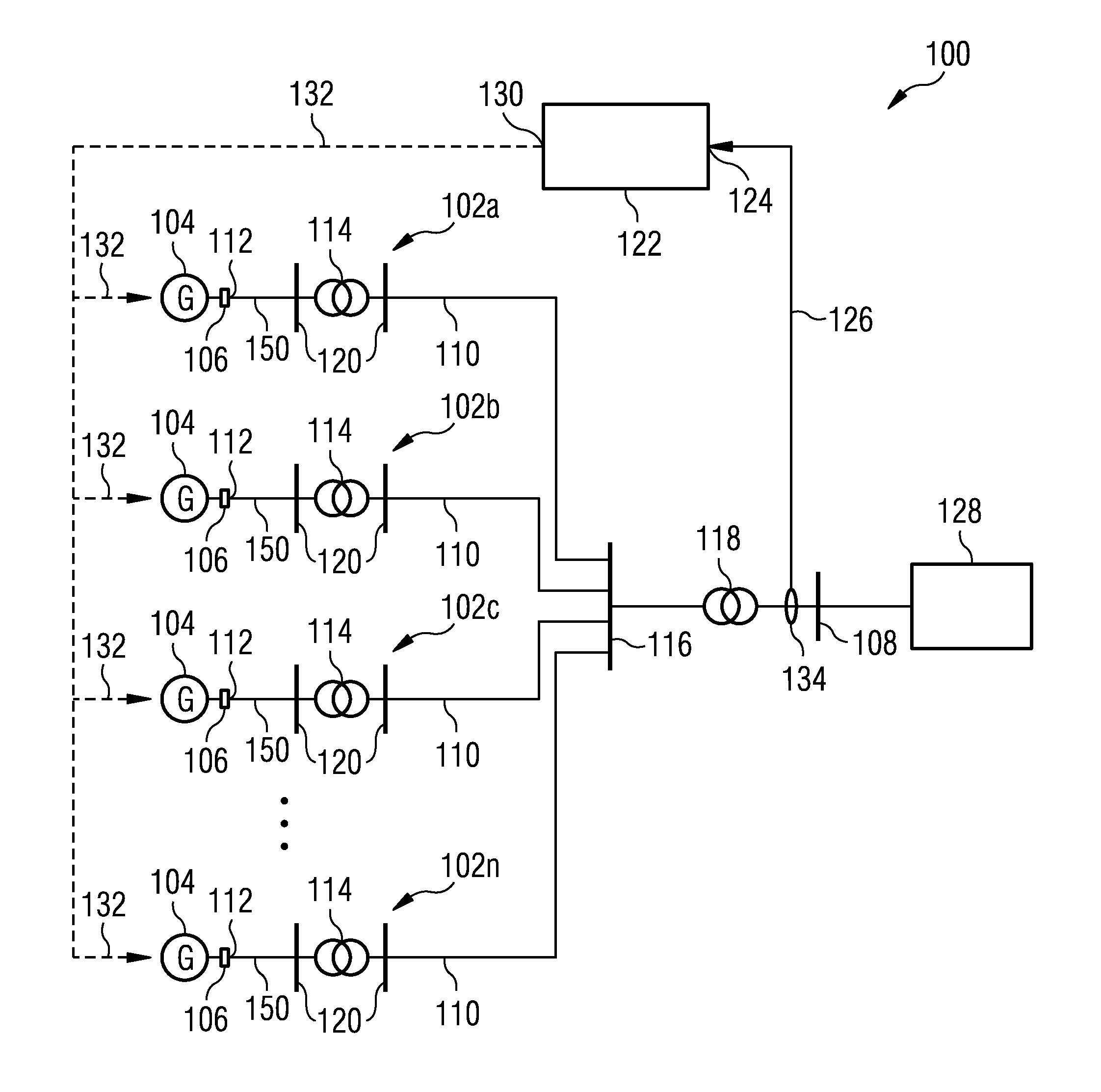
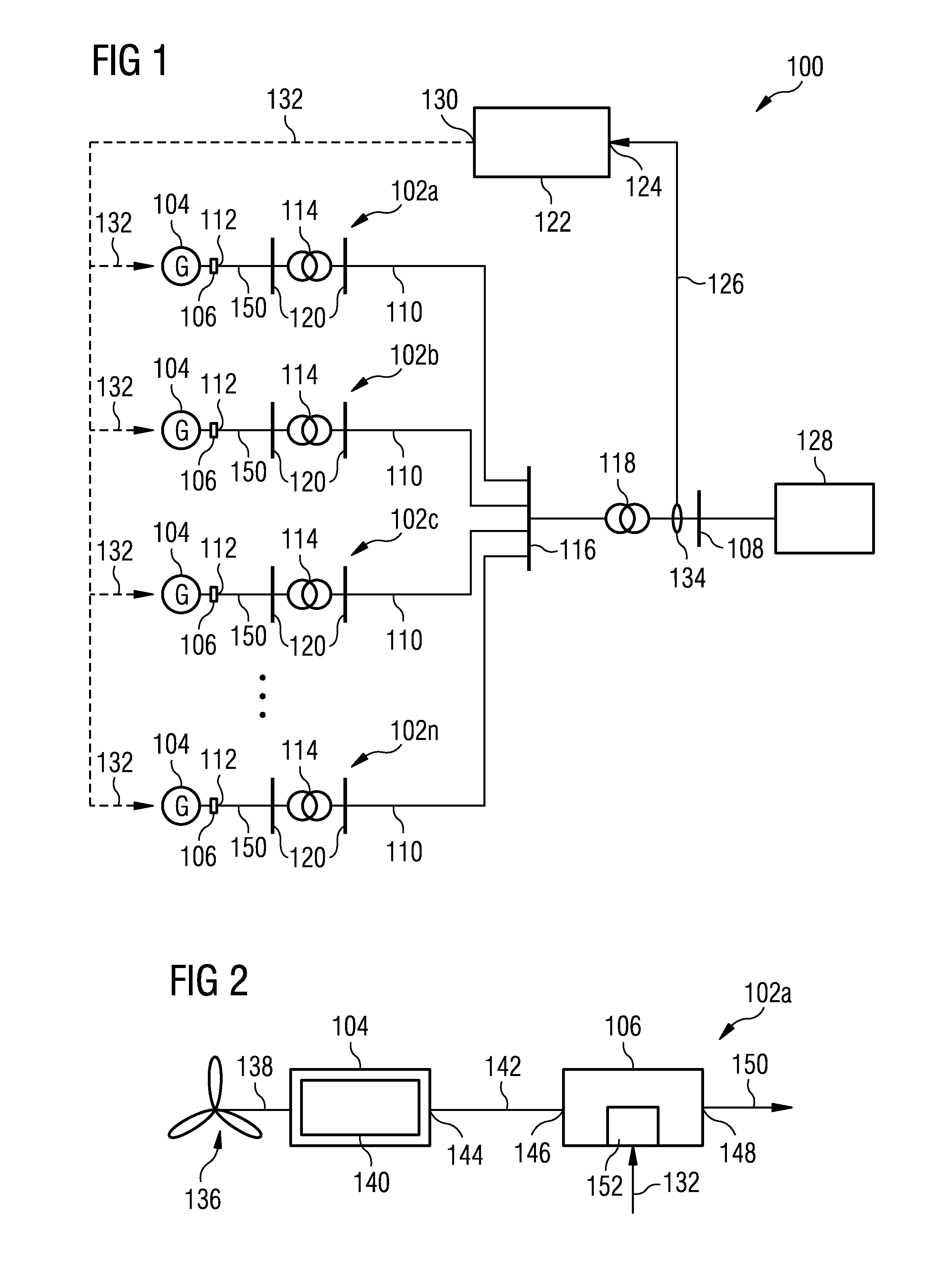
[0061]FIG. 1 shows a power generation park 100 in accordance with embodiments of the herein disclosed subject-matter.

[0062]The power generation park 100 comprises at least two, e.g. n power generation devices 102a, 102b, 102c . . . 102n. At least one of the power generation devices 102a-102n is configured according to embodiments of the herein disclosed subject-matter. For example, in an embodiment all power generation devices 102a-102n are configured according to embodiments of the herein disclosed subject-matter.

[0063]The power generation park 100 in FIG. 1 is, in accordance with an embodiment, a wind park and the power generation devices 102a-102n are wind turbine devices. Each wind ...


PUM


Abstract

A power generation park is provided including a power output for providing electrical output power to an electricity network. A power generation device includes a converter device configured for receiving input power from a power generator and providing, in response hereto, the electrical output power to the power output. The power generation park further includes a controller configured for receiving an oscillation indicating signal indicative of a power oscillation in the electricity network, the controller further configured for providing a damping control signal in response to the oscillation indicating signal, the converter device configured for modulating the electrical output power in response to the damping control signal so as to damp the power oscillation in the electricity network.

Description

[0001]The present invention relates to the field of converter-based power generation devices, i.e. power generation devices which include a converter. In particular, the present invention relates to the field of wind turbine devices.[0002]ART BACKGROUND[0003]Power oscillations typically occur in large interconnected power systems, where two or more areas are interconnected through relatively weak alternating current (AC) transmission lines. These power oscillations are also referred to as interarea oscillations. Whether or not an oscillation is stable or unstable is a system property. Hence it is not the contingency initiating the oscillation that determines the necessary level of damping. Rather, the necessary level of damping depends on the state of the power system, i.e. operating condition, controller tuning, transmission lines, the generators in service, etc.[0004]If a power oscillation between two areas of a power system is excited, the rotor angles of synchronous machines in ...

Claims


Application Information

Patent Timeline
IPC IPC(8): F03D9/00H02P9/02
CPCH02P9/02F03D9/005F03D9/257H02J2300/28H02J2300/22H02J3/381H02J3/241H02J3/48H02J3/50Y02E10/76Y02E10/72
Inventor ANDRESEN, BJORNFRYDENSBJERG, MICHAEL NOERTOFTKNUPPEL, THYGE
Owner SIEMENS GAMESA RENEWABLE ENERGY AS
Why Eureka
Try Eureka