Eureka AIR delivers breakthrough ideas for toughest innovation challenges, trusted by R&D personnel around the world.

Integrating sphere

Active Publication Date: 2014-12-11
HONDA MOTOR CO LTD
View PDF14 Cites 5 Cited by
  • Summary
  • Abstract
  • Description
  • Claims
  • Application Information

AI Technical Summary

Benefits of technology

The patent aims to address issues by providing an integrating sphere that measures the color of an object using light from a light source that is reflected on the interior wall of a structure. This helps to prevent damage to the sphere and ensure accurate measurements.

Problems solved by technology

Nevertheless, the release strength of the white coating material is still insufficient even using binders and what is worse, binders can be discolored by heat or ultraviolet light.
Therefore, if a measuring object is susceptible to heat like an organic material, it can be discolored during measurement, rendering it difficult to measure the color of the object accurately.
However, the spherical inner wall is still susceptible to be degraded by infrared light radiated from the light source or heat from the infrared light or light source.
Disadvantageously, spraying requires large facilities.

Method used


Image

  • Integrating sphere
  • Integrating sphere
  • Integrating sphere

Examples


first embodiment

[0021]An integrating sphere according to a first embodiment of this invention will now be explained with reference to the attached drawings.

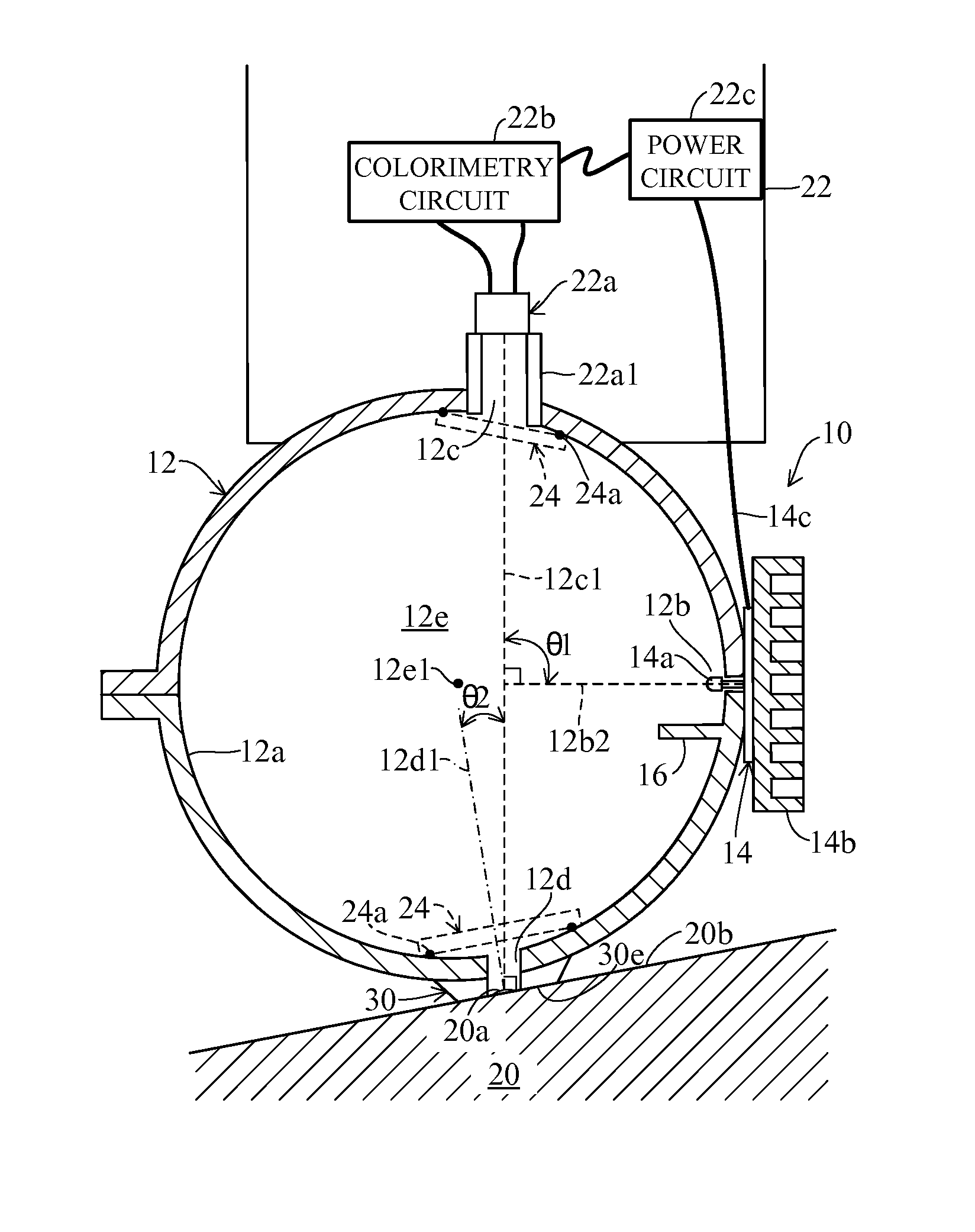
[0022]FIG. 1 is an overall schematic view of the integrating sphere according to the first embodiment of this invention.

[0023]In FIG. 1, symbol 10 indicates an integrating sphere. The integrating sphere 10 includes a structure 12 of a spherical shape as shown. The structure 12 has a spherical inner wall (surface) 12a coated with a diffuse reflective coating and spherically-curved with a predetermined curvature, and is formed with an input (incident) port 12b, an output (emission) port 12c and a measuring (detector) port 12d thereat.

[0024]The inner wall 12a of the structure 12 is applied with diffuse reflective coating by a known technique so as to allow a light to be diffuse-reflected on the wall (surface) 12a. The inner wall 12a forms a spherical space 12e in the structure 12.

[0025]The structure 12 is equipped with an LED circuit board 14. The ...

second embodiment

[0052]Next, an integrating sphere according to a second embodiment of this invention will now be explained with reference to the attached drawings.

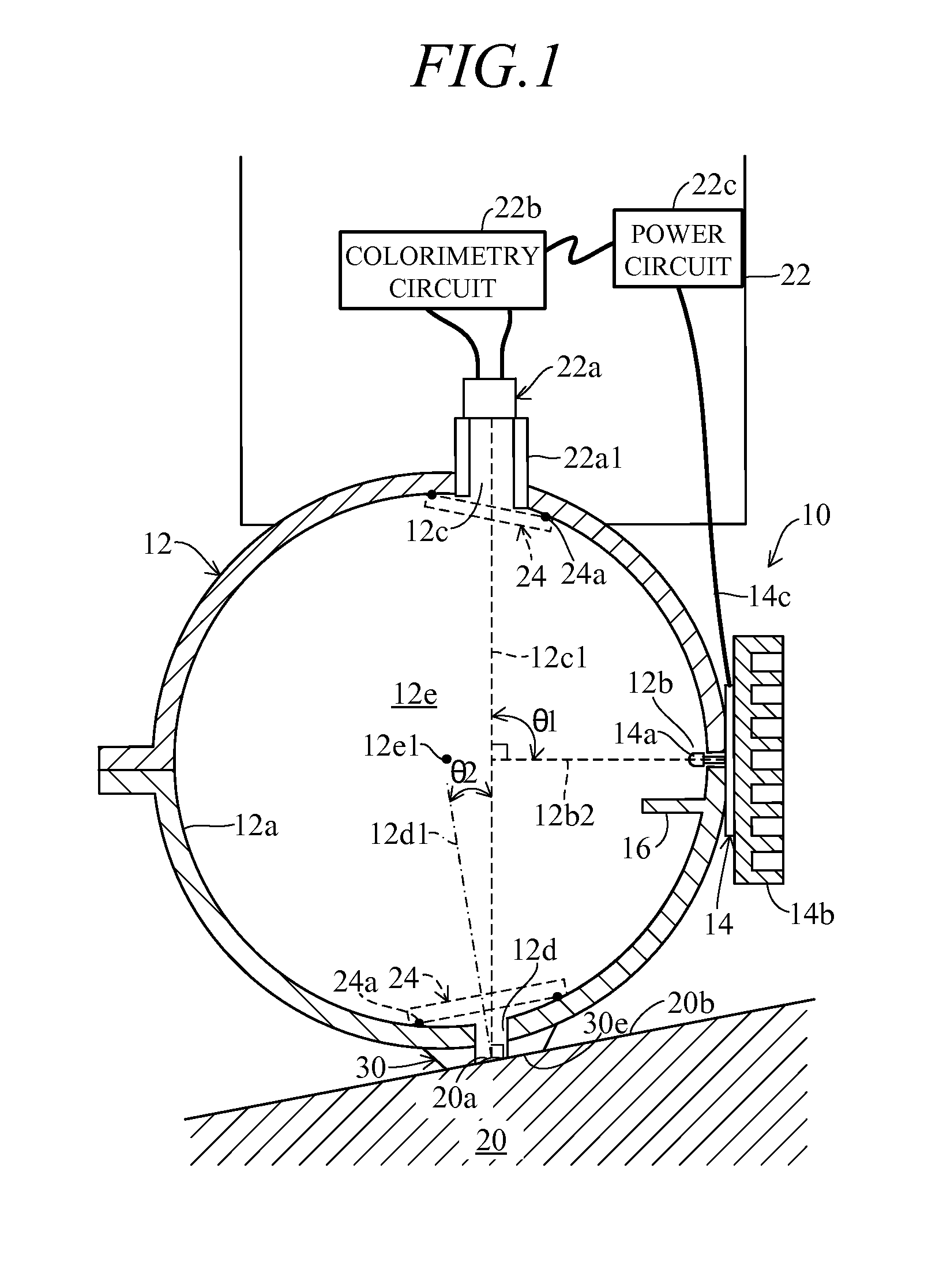
[0053]FIG. 2 is an overall schematic view of the integrating sphere according to the second embodiment of this invention.

[0054]The integrating sphere according to the second embodiment, now assigned with symbol 10a, has basically the same structure as that of the integrating sphere 10 according to the first embodiment. Therefore, the second embodiment will be explained with focus on the points of difference from the first embodiment, while marking the same elements with the same symbols and omitting the explanation.

[0055]In the integrating sphere 10a according to the second embodiment, the light-emitting device 14a is of a surface-mounting type and, for example in the case of white LED, is made of a blue LED and an yellow illuminant. As shown, the light-emitting device 14a is configured to radiate white light into the spherical space 12e ...

third embodiment

[0073]Next, an integrating sphere according to a third embodiment of this invention will now be explained with reference to the attached drawings.

[0074]FIG. 8 is an explanatory view partially showing the integrating sphere, now assigned with symbol 10b, according to the third embodiment of this invention.

[0075]Explaining the third embodiment with focus on the points of difference from the second embodiment, in the integrating sphere 10b according to the third embodiment, the LED circuit board 14 is configured to have a shell-type light-emitting device 14a similarly to the first embodiment, unlike the light-emitting device 14a of the surface-mounting type of the second embodiment shown in FIG. 2.

[0076]More specifically, as shown in FIG. 9, the light-emitting device 14a has a shell like shape sealed with a epoxy resin 14a1 and in the case of white LED, for example, is made of a blue LED and a yellow illuminant, and is configured to radiate white light to the spherical space 12e formed...


PUM


Abstract

In an integrating sphere including a structure having a spherical inner wall that forms a spherical space, there are provided an LED circuit board equipped at one end with a light-emitting device adapted to radiate a light in the space at an input port formed at the structure to be diffuse-reflected on the spherical inner wall and equipped at other end with a heat sink, a measuring port formed at the structure to pass the light diffuse-reflected on the spherical inner wall on a measuring object, an output port formed at the structure to output a reflected light of the diffuse-reflected light passing the measuring port and reflected on the measuring object outside, and a detector adapted to be detachably connected to the output port to receive the outputted reflected light.

Description

BACKGROUND[0001]1. Technical Field[0002]This invention generally relates to an integrating sphere, more particularly to a structure thereof.[0003]2. Related Art[0004]An integrating sphere used in analysis of luminous flux of a light source or color of a measuring object is generally provided with a structure having a spherical inner wall (surface) wherein a light radiated from the light source repeats diffuse reflection on the spherical inner wall to be spatially-integrated, for example, as disclosed in Japanese Patent No. 4,272,629.[0005]Specifically, in a conventional integrating sphere other than that disclosed in the reference, binders have been used to enhance release strength of a white coating material, as the release strength of the white coating material is significantly low in powder foam. Nevertheless, the release strength of the white coating material is still insufficient even using binders and what is worse, binders can be discolored by heat or ultraviolet light. Takin...

Claims


Application Information

Patent Timeline
IPC IPC(8): G01N21/25
CPCG01N21/251G01N21/255G01J1/08G01J3/501G01N2201/065
Inventor HARADA, HIRONORIMATSUMOTO, KENJI
Owner HONDA MOTOR CO LTD
Why Eureka
Eureka Blog
Learn More