

Charging device with exhaust gas temperature control device
- Summary
- Abstract
- Description
- Claims
- Application Information
AI Technical Summary
Benefits of technology
Problems solved by technology
Method used
Image

Examples
Embodiment Construction
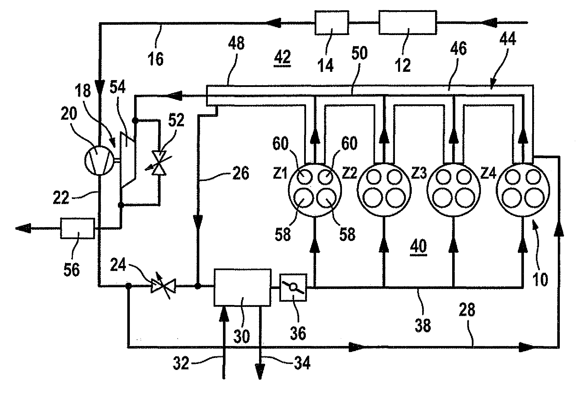
[0019]There will be seen from the illustration shown in FIG. 1 a flow diagram of a charging device of one-stage construction with a cooling air branch downstream of the compressor part of the charging device.
[0020]As shown in the flow diagram illustrated in FIG. 1, ambient air flows toward an air filter 12 of an internal combustion engine 10. Internal combustion engine 10 may be either a self-ignition internal combustion engine or a spark-ignition internal combustion engine. Arranged downstream of air filter 12 is an air mass meter 14. From the latter the air flows via a first line 16 to a compressor part 20 of a charging device 18 which, in this example embodiment, is of a one-stage construction. Once compressed, the compressed fresh air flows via a second line 22 to a first regulating valve 24. Downstream of first regulating valve 24 there is the entry point of a third line 26, while a fourth line 28 branches off upstream of first regulating valve 24.
[0021]Depending on the positio...
PUM
 Abstract
Description
Claims
Application Information