Display device

a display device and display technology, applied in the direction of electrical apparatus construction details, instruments, casings/cabinets/drawers, etc., can solve the problems of increased thickness and weight of the display device, unfavorable thinning of the product, light leakage at the dark state, etc., to achieve heat dissipation efficiency, improve the appearance, and improve the effect of structural strength

Inactive Publication Date: 2014-12-11
INNOLUX CORP
View PDF41 Cites 9 Cited by
  • Summary
  • Abstract
  • Description
  • Claims
  • Application Information

AI Technical Summary

Benefits of technology

[0019]As mentioned above, in the display device of the invention, the carrying member carries the display panel, the circuit connecting boards are disposed adjacent to the carrying member and physically and electrically connected to the display panel, and the shortest distance between two adjacent circuit connecting boards is between 0.1 mm and 20 mm. Besides, the control circuit board is electrically connected to the display panel through the circuit connecting boards, and the front frame member is disposed at the outer edge of the carrying member and connected to the carrying member. Moreover, the front frame member includes a turning portion and an extending portion, and the thickness of the turning portion is greater than that of the extending portion. Due to the special design of the front frame member of the invention, the display device can be made thinner and have higher structural strength and heat dissipation efficiency, and also the compressing light leakage can be reduced.

Problems solved by technology

However, because the more circuit connecting boards and control circuit boards take more space, the module of the prior art needs to be increased in thickness to provide more locking space for the front frame, but this will increase the thickness and weight of the display device and is unfavorable for the thinning tendency of the product.
Besides, because the evenness of the front frame of the one-piece metal material is not sufficient for the LCD apparatus of the current wide-viewing-angle design (e.g. MVA, IPS, FFS), the display panel thereof will undergo some compression, pull or push, and thus cause the light leakage at the dark state (e.g. Pinch Mura).

Method used


Image

  • Display device
  • Display device
  • Display device

Examples


Embodiment Construction

[0026]The present invention will be apparent from the following detailed description, which proceeds with reference to the accompanying drawings, wherein the same references relate to the same elements.

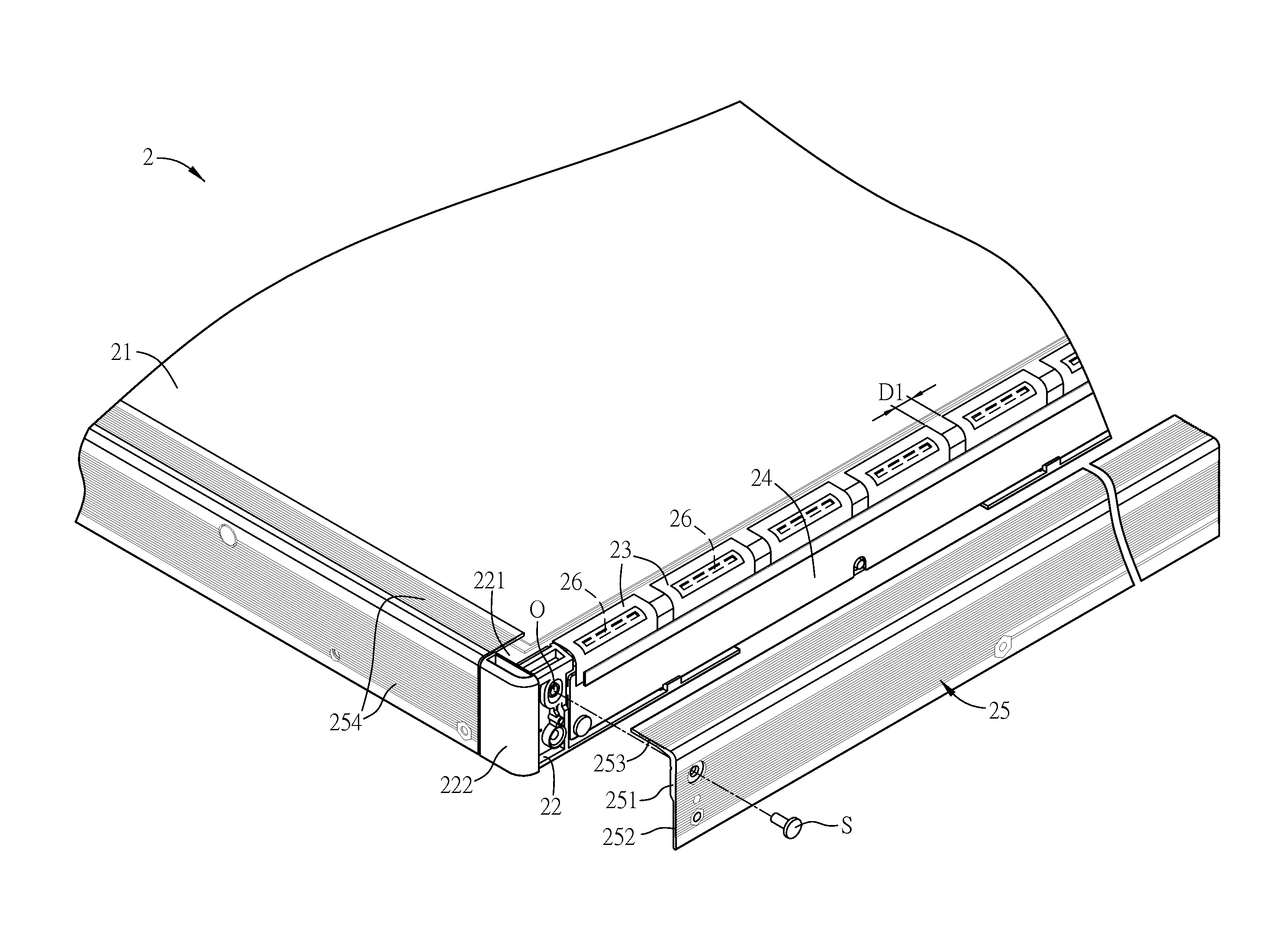
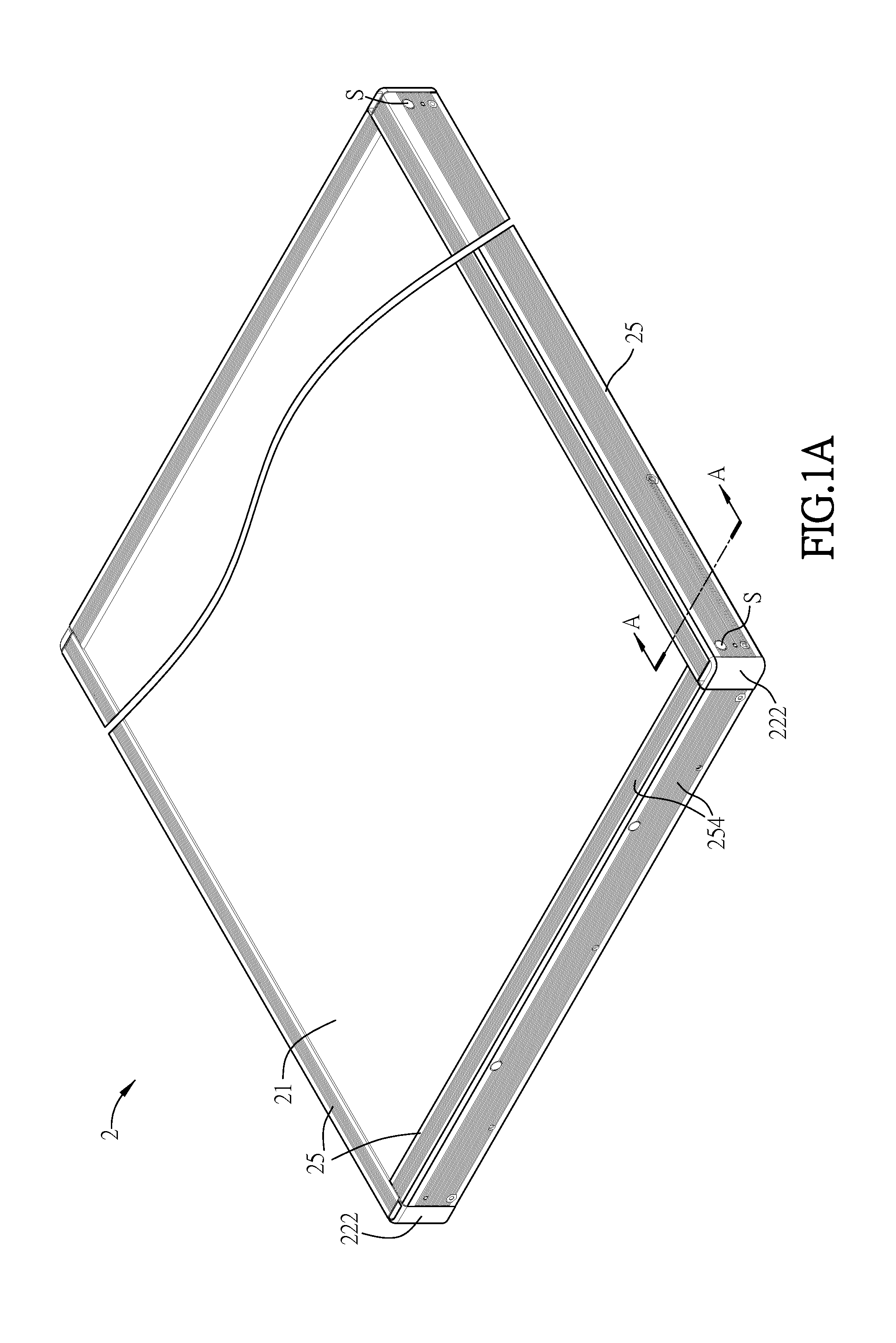
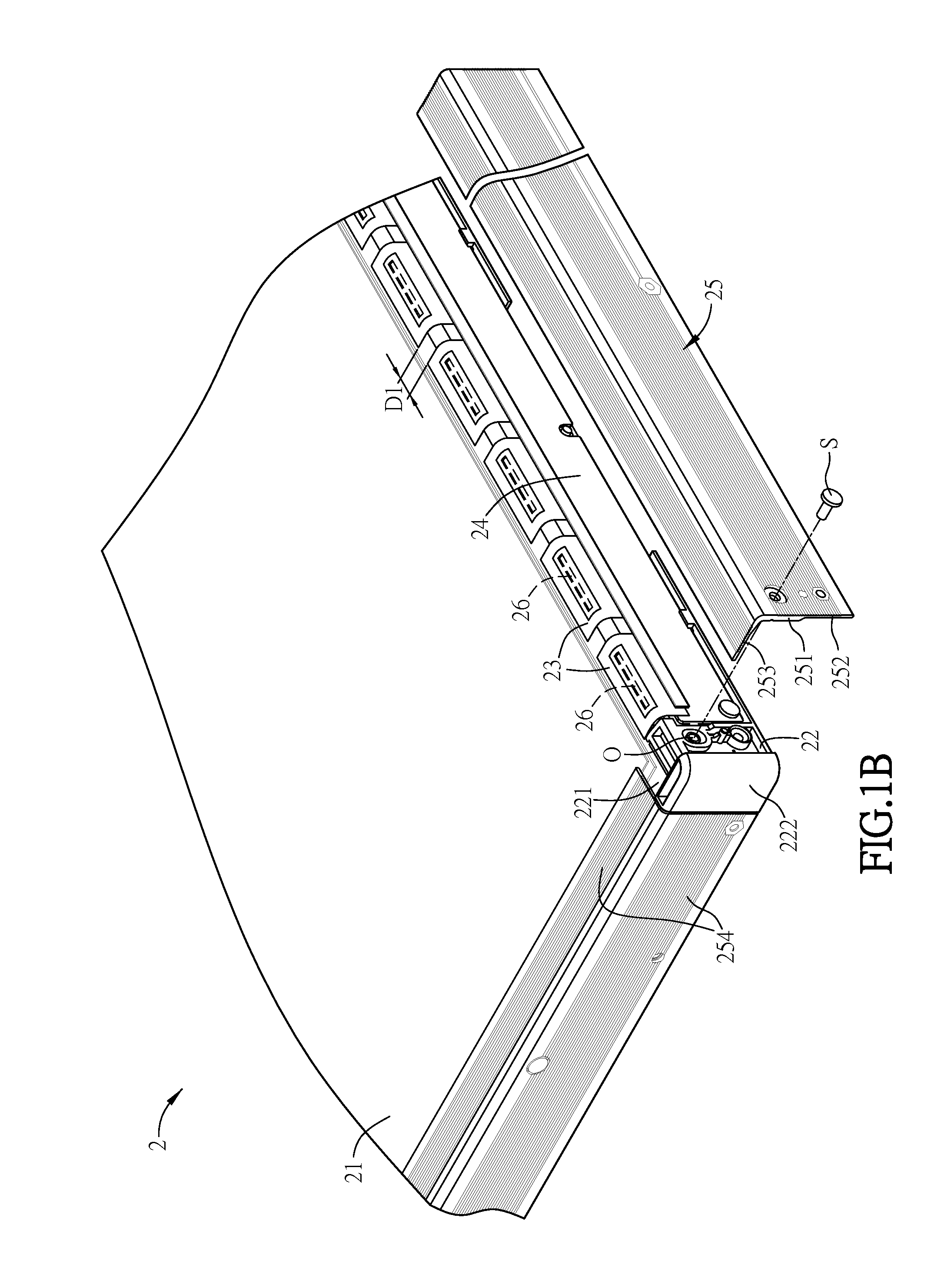
[0027]FIG. 1A is a schematic diagram of a display device 2 according to a preferred embodiment of the invention, FIG. 1B is a partial exploded diagram of the display device 2 in FIG. 1A, FIG. 1C is a sectional diagram of the display device 2 taken along the line A-A in FIG. 1A, and FIG. 1D is a schematic diagram of a front frame member 25 in FIG. 1A.

[0028]As shown in FIGS. 1A to 1D, the display device 2 includes a display panel 21, a carrying member 22, a plurality of circuit connecting boards 23, a control circuit board 24 and at least a front frame member 25.

[0029]The display panel 21 can be an LCD panel or an OLED panel. In this embodiment, the display panel 21, as shown in FIG. 1C, includes a first substrate 211 and a second substrate 212 which is disposed opposite to the first su...


PUM


Abstract

A display device comprises a display panel, a carrying member, a plurality of circuit connecting boards, a control circuit board and at least a front frame member. The carrying member carries the display panel. The circuit connecting boards are disposed adjacent to the carrying member and physically and electrically connected to the display panel. The shortest distance between the two adjacent circuit connecting boards is between 0.1 mm and 20 mm. The control circuit board is disposed adjacent to the carrying member and electrically connected to the circuit connecting boards, and electrically connected to the display panel through the circuit connecting boards. The front frame member is disposed at the outer edge of the carrying member and connected to the carrying member, and includes a turning portion and an extending portion. The thickness of the turning portion is greater than that of the extending portion.

Description

CROSS REFERENCE TO RELATED APPLICATIONS[0001]This Non-provisional application claims priority under 35 U.S.C. §119(a) on Patent Application No(s). 102120103 filed in Taiwan, Republic of China on Jun. 6, 2013, the entire contents of which are hereby incorporated by reference.BACKGROUND OF THE INVENTION[0002]1. Field of Invention[0003]The invention relates to a display device.[0004]2. Related Art[0005]Flat display apparatuses, such as liquid crystal display (LCD) apparatuses or organic light emitting display apparatuses, having advantages such as low power consumption, less heat, light weight and non-radiation, are widely applied to various electronic products and gradually take the place of cathode ray tube (CRT) display apparatuses.[0006]For the module design of a display panel, a high-resolution display panel usually accompanies more data lines and driver ICs as well as more circuit connecting boards and a larger control circuit board. Accordingly, the high-resolution display panel...

Claims


Application Information

Patent Timeline
Patent Type & Authority Applications(United States)
IPC IPC(8): H05K1/14H05K1/02H05K7/20
CPCH05K1/142H05K2201/04H05K1/0201H05K7/20963H05K1/147H05K1/189H05K2201/10136G02F1/133308G02F1/133385G02F1/13332G02F1/133328
Inventor HUANG, WEI-SHIHAI, KUN-CHIHFENG, SHIH-YUAN
Owner INNOLUX CORP
Why Eureka
Try Eureka