
Current equalizing busbar

a current equalizing and busbar technology, applied in the direction of laminated busbars, power conversion systems, electrical equipment, etc., can solve the problems of high requirement for line-feeding manner of copper busbars, large size and high cost of copper busbars, and difficulty in installing symmetrical copper busbars. , to achieve the effect of good current equalizing effect, simple structure and high reliability

Active Publication Date: 2014-12-11
DELTA ELECTRONICS INC
View PDF4 Cites 13 Cited by
  • Summary
  • Abstract
  • Description
  • Claims
  • Application Information

AI Technical Summary

Benefits of technology

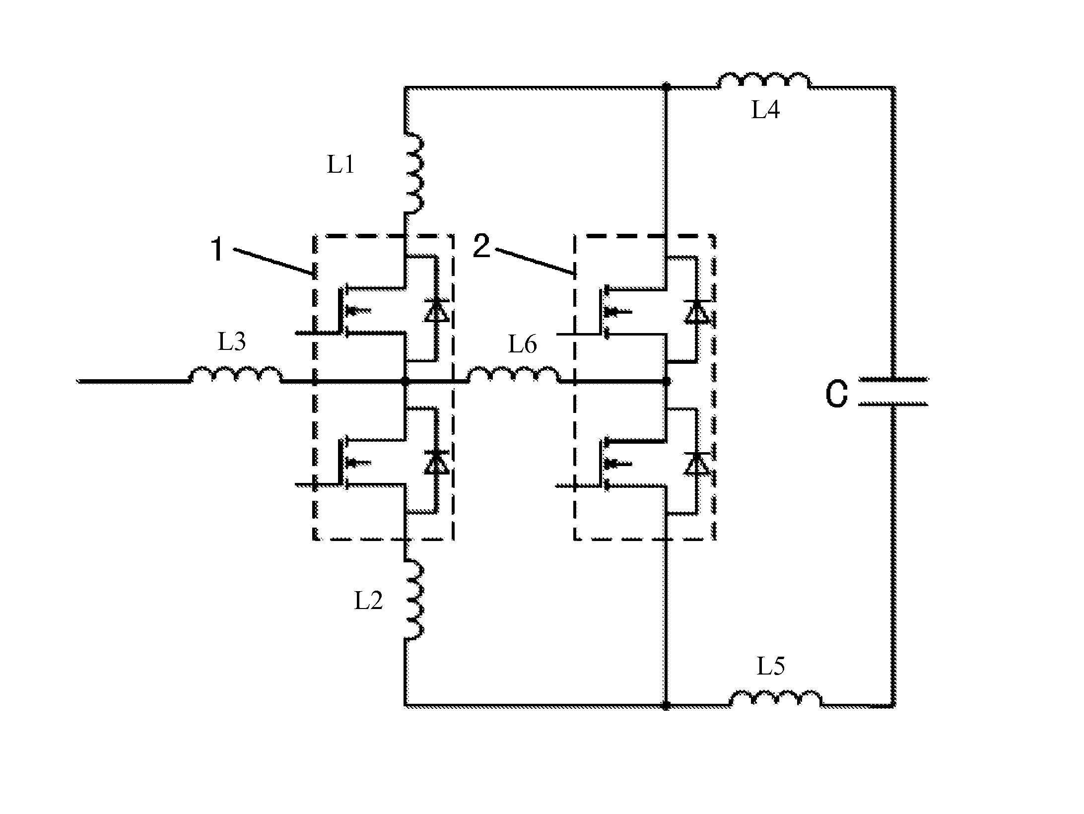
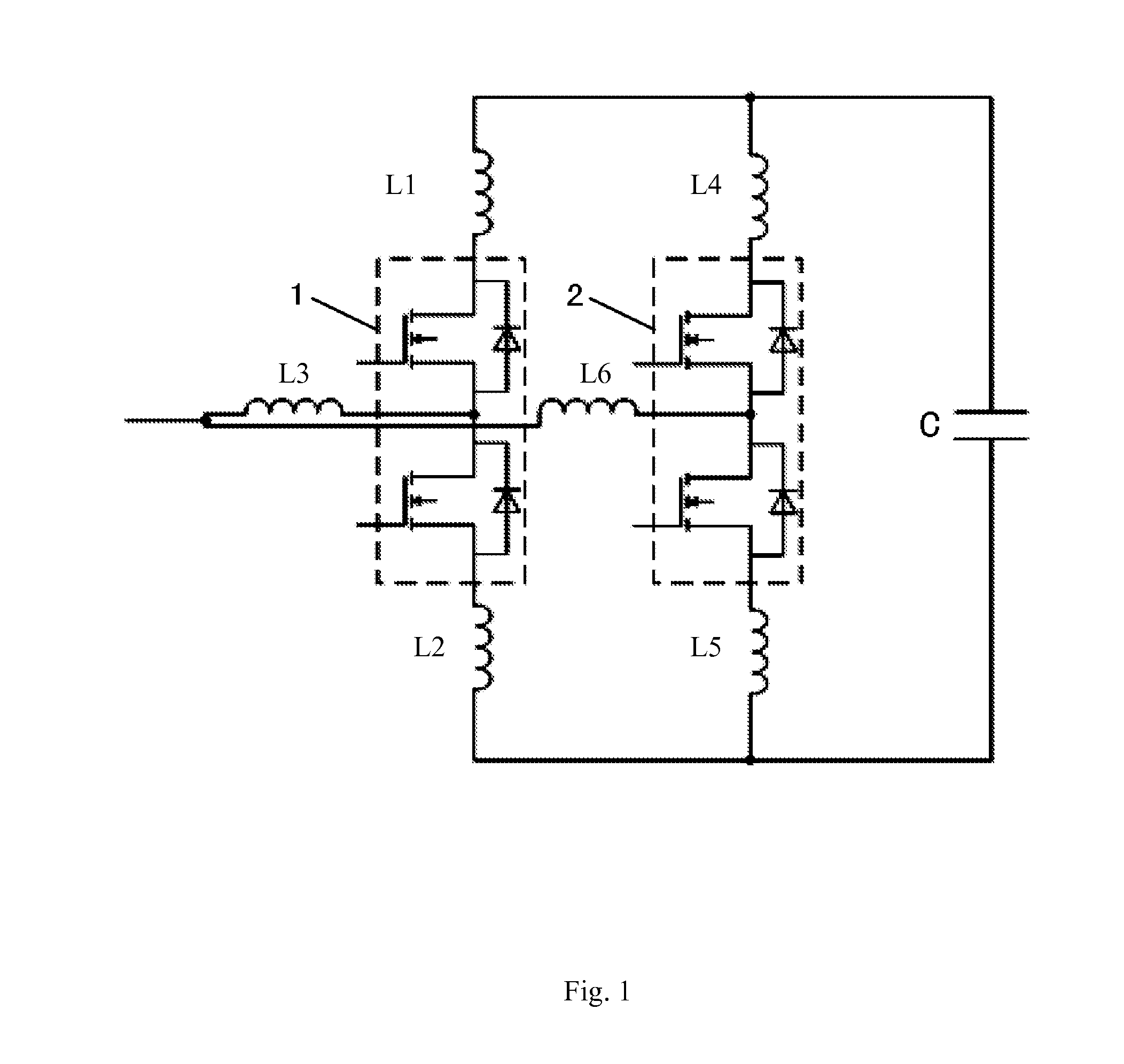
The present application provides a current equalizing busbar arrangement that can effectively equalize the current, have a simple design, and make it easy to design the system. The current equalizing busbars have a reliable performance and are widely applicable in large power converters.

Problems solved by technology

Therefore, due to cost and semiconductor device manufacturing process level, it requires that power components (for example, IGBTs, i.e., Insulated Gate Bipolar Transistors) are used in parallel to meet the design output requirements.
For parallelling IGBTs, an important issue is how to equalizing current among the components.
However, this arrangement manner requires symmetrically design of AC busbars, resulting in large size and high cost of copper busbars and high requirement for line-feeding manner of the copper busbars.
In addition, it is difficult to install these symmetrical copper busbars, which does not facilitate system design.
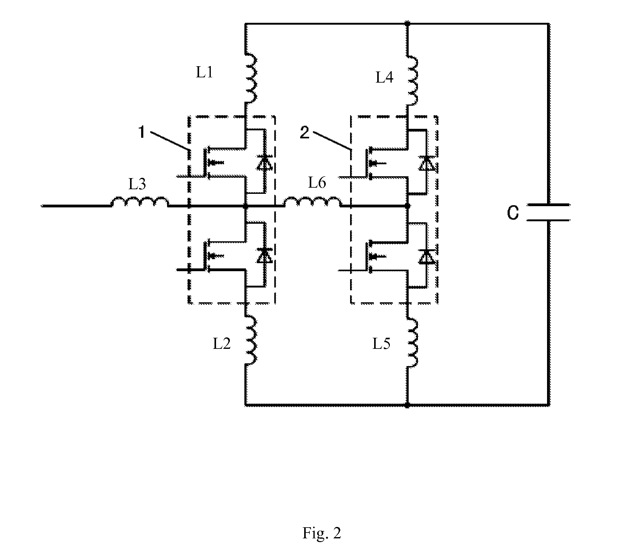
From FIG. 2 and FIG. 3, it can be seen that, although this design is simple and the installation is relatively easy in comparison with the previously mentioned manner, the parasitic inductances caused by the AC busbar with respect to power modules 1 and 2 are different, resulting in a dissatisfactory current equalizing effect.
Therefore, the arrangements in the prior art either have a simple structure while having a poor current equalizing effect, or have a good current equalizing effect while having a complicated design, large volume and stiff line-feeding manner, and thus affecting the overall system design.

Method used


Image

  • Current equalizing busbar
  • Current equalizing busbar
  • Current equalizing busbar

Examples


Embodiment Construction

[0023]Hereinafter, embodiments of the present application are described in detail. It should be noted that the embodiments are only illustrative, not intend to limit the present application.

[0024]The present application will now be described more fully hereinafter with reference to the accompanying drawings, in which exemplary embodiments of the application are shown. This application may, however, be embodied in many different forms and should not be construed as limited to the embodiments set forth herein. Rather, these embodiments are provided so that this disclosure will be thorough and complete, and will fully convey the scope of the application to those skilled in the art. Like reference numerals refer to like elements throughout the context.

[0025]The terminology used herein is for the purpose of describing particular embodiments only and is not intended to limit the application. As used herein, the singular forms “a”, “an” and “the” are intended to include the plural forms as...


PUM

PropertyMeasurementUnit
currentaaaaaaaaaa
inductanceaaaaaaaaaa
distancesaaaaaaaaaa

Abstract

The present application discloses a current equalizing busbar for a converter comprising: a direct current busbar connected to a DC terminal of the converter and positive terminals and negative terminals of respective power modules; and an alternate current busbar connected to AC terminals of the respective power modules and a load; wherein, when the converter operates, a sum of an inductance caused by the DC busbar between the DC terminal and a positive terminal or a negative terminal of a power module and an inductance caused by the AC busbar between the load and an AC terminal of the power module is equal to a sum of an inductance caused by the DC busbar between the DC terminal and positive terminals or negative terminals of other power modules and an inductance caused by the AC busbar between the load and AC terminals of said other power modules.

Description

CROSS REFERENCE TO RELATED APPLICATIONS[0001]The present application claims priority under 35 U.S.C. §119 to Chinese Patent Application No. 201310228230.9, filed on Jun. 7, 2013, the entire content of which is incorporated herein by reference.TECHNICAL FIELD[0002]The present application relates to a busbar arrangement, and more particularly to a current equalizing busbar for a converter.BACKGROUND ART[0003]Wind energy as a kind of clean, non-polluting and renewable energy attracts considerable attention. After many years developing, the proportion of wind power is increasing year by year, while the capacity of a single wind generator gets bigger and bigger. The capacity of a converter being as a main component of a wind generator increases rapidly, for example, the capacity of foreign mainstream models from 500˜1000 KW in 2000 year to 2˜3 MW in 2009 year, currently being developed to 8˜10 MW; the capacity of domestic mainstream models from 600˜1000 KW in 2005 to 850˜2000 KW in 2009,...

Claims


Application Information

Patent Timeline
Patent Type & Authority Applications(United States)
IPC IPC(8): H01B5/02H02M7/5387H02M7/493
CPCH02M7/5387H01B5/02H02G5/005H02M7/493H02M7/003
Inventor SUN, ZONGYUCHEN, JUNXU, TENGLIU, LINKUANG, JINGXIAN
Owner DELTA ELECTRONICS INC
Learn More