X-ray generator and x-ray imaging apparatus
a generator and x-ray technology, applied in the direction of instruments, x-ray tubes, material analysis using wave/particle radiation, etc., can solve the problem that the x-ray generation efficiency of transmission x-ray generators that irradiate a transmission target with electrons to generate x-rays is generally extremely low, and achieve the effect of improving the x-ray generation efficiency
- Summary
- Abstract
- Description
- Claims
- Application Information
AI Technical Summary
Benefits of technology
Problems solved by technology
Method used
Image

Examples
first embodiment
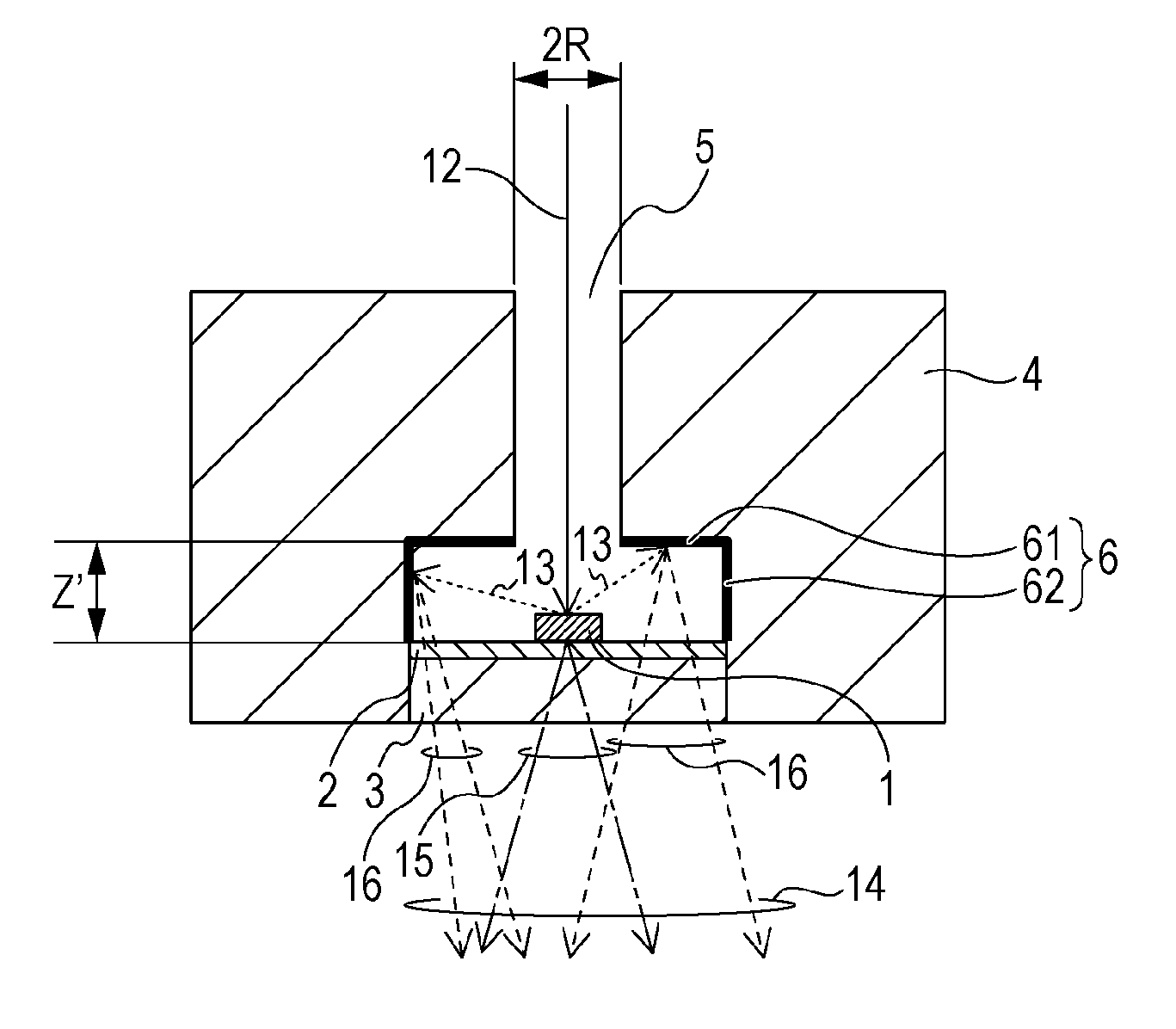
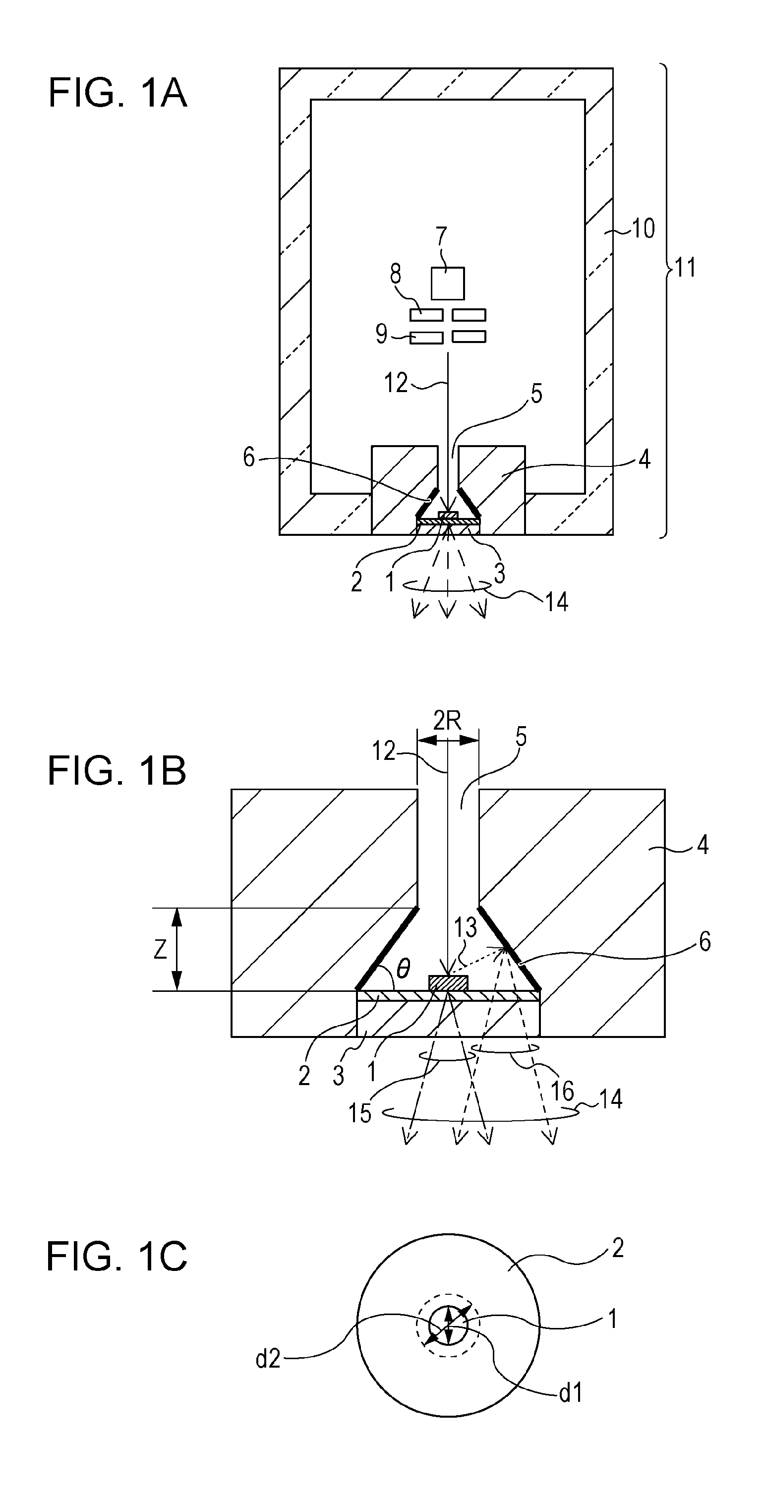
[0036]FIG. 1A is a schematic diagram of a transmission X-ray generating tube (hereinafter referred to as an X-ray tube) 11 of a first embodiment of the present invention. FIG. 1B is an enlarged view of the vicinity of the target 1 in FIG. 1A. FIG. 1C is a plan view of the target unit in FIG. 1A, as viewed from the target side.
[0037]A vacuum container 10 is used to maintain the interior of the X-ray tube 11 under vacuum and is formed of a glass or ceramic material or the like. The degree of vacuum in the vacuum container 10 is preferably about 10−4 to 10−8 Pa. The vacuum container 10 has an opening, to which an electron-passage forming member 4 having an electron passage 5 is joined. The substrate 3 is joined to the inner wall surface of the electron passage 5 to tightly seal the vacuum container 10.
[0038]An electron emission source 7 is disposed in the vacuum container 10 so as to face the target 1. The electron emission source 7 may be a tungsten filament, a hot cathode, such as an...
second embodiment
[0070]This embodiment differs from the first embodiment in the shapes of the electron-passage forming member 4 and the electron passage 5 and is the same in commonalities other than the shapes of the electron-passage forming member 4 and the electron passage 5. The target unit can be any of the target units described in the first embodiment.
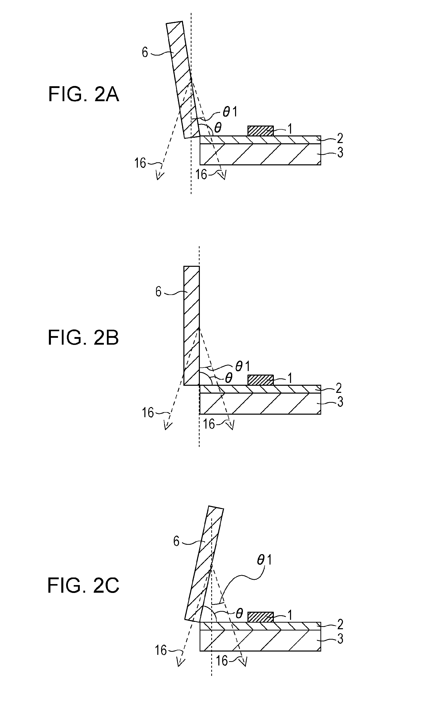
[0071]FIG. 5A is an enlarged view of the vicinity of the target 1 of this embodiment. The electron passage 5 whose both ends are open is formed by surrounding the periphery with the electron-passage forming member 4. The electron passage 5 has an upward convex arc cross-sectional shape in the direction perpendicular to the target 1 when the target 1 is assumed to be at the lower side. Furthermore, the inner wall surface of the enlarged-cross-sectional-area region of the electron passage 5 serves as the secondary-X-ray generation surface 6.
[0072]Since the cross-sectional shape of the secondary-X-ray generation surface 6 is an upward convex arc sha...
third embodiment
[0073]This embodiment differs from the first embodiment in the shapes of the electron-passage forming member 4 and the electron passage 5 and is the same in commonalities other than the shapes of the electron-passage forming member 4 and the electron passage 5. The target unit can be any of the target units described in the first embodiment.
[0074]As shown in FIG. 5B, the electron passage 5 has a downward convex arc cross-sectional shape in the direction perpendicular to the target 1 when the target 1 is assumed to be at the lower side.
[0075]Since the cross-sectional shape of the secondary-X-ray generation surface 6 is a downward convex arc shape when the target 1 is assumed to be at the lower side, the X-rays 16 generated at the secondary-X-ray generation surface 6 is absorbed in the secondary-X-ray generation surface 6 at a low ratio, so that the amount of X-rays 16 extracted can be increased.
[0076]A preferable range of the area in which the secondary-X-ray generation surface 6 is ...
PUM
| Property | Measurement | Unit |
|---|---|---|
| angle | aaaaa | aaaaa |
| voltage | aaaaa | aaaaa |
| atomic numbers | aaaaa | aaaaa |
Abstract
Description
Claims
Application Information
PatSnap Eureka turns technology decisions into work you can execute. Powered by our Innovation Knowledge Graph, it runs expert workflows across engineering, life sciences, materials and intellectual property. Get your review-ready output in minutes.


