Device and method for protecting a wind generator in the event of violent winds and wind generator provided with such a device

Inactive Publication Date: 2014-12-18
CUZENARD PASCAL
View PDF5 Cites 5 Cited by
  • Summary
  • Abstract
  • Description
  • Claims
  • Application Information

AI Technical Summary

Benefits of technology

[0015]An object of the present invention is a device for protecting the wind generator in the event of violent winds which comprises, according to a first feature, a part for connecting a wind generator blade to the hub of said wind generator. The blade-connecting part-hub assembly forming the rotor of said wind generator, which comprises one or several blade(s), and as many connecting parts as blades, is driven in a rotating movement by the wind thrust force, driving a power transmission system which drives in turn an electrical generator which produces electricity. The power transmission system and the generator are housed within a nacelle rotatably mounted on a support tower via an orientation mechanism behind the rotor. Both ends of said connecting part, one connected to the hub and the other connected to the blade, are characterized by the fact that their respective central axis forms a non-zero angle with respect to each other, the connecting part is adapted to be connected to the hub via a drive mechanism such that said connecting part

Problems solved by technology

These devices require specific structural arrangements for the blades which, during their service life of about 20 years, undergo up to 108 load cycles which, are partly highly variable and non-uniform.
These structural arrangements adversely affect the rigidity and the strength of the blades, and thus their reliability, in addition to being costly in maintenance.
The aerodynamic load due to the wind of the rotor actively inclined with respect to the rotation plane according to the wind speed is particularly complex, which makes this device difficult to design and implement.
In addi

Method used


Image

  • Device and method for protecting a wind generator in the event of violent winds and wind generator provided with such a device
  • Device and method for protecting a wind generator in the event of violent winds and wind generator provided with such a device
  • Device and method for protecting a wind generator in the event of violent winds and wind generator provided with such a device

Examples


Embodiment Construction

[0075]In the following detailed descriptions, many specific details are defined so as to provide a thorough understanding of the conceptual arrangements representing the essential functions of the present invention. The parts, systems, mechanisms, processes, interfaces and circuits well known to the person skilled in the art are not presented here in order not to obfuscate the present invention.

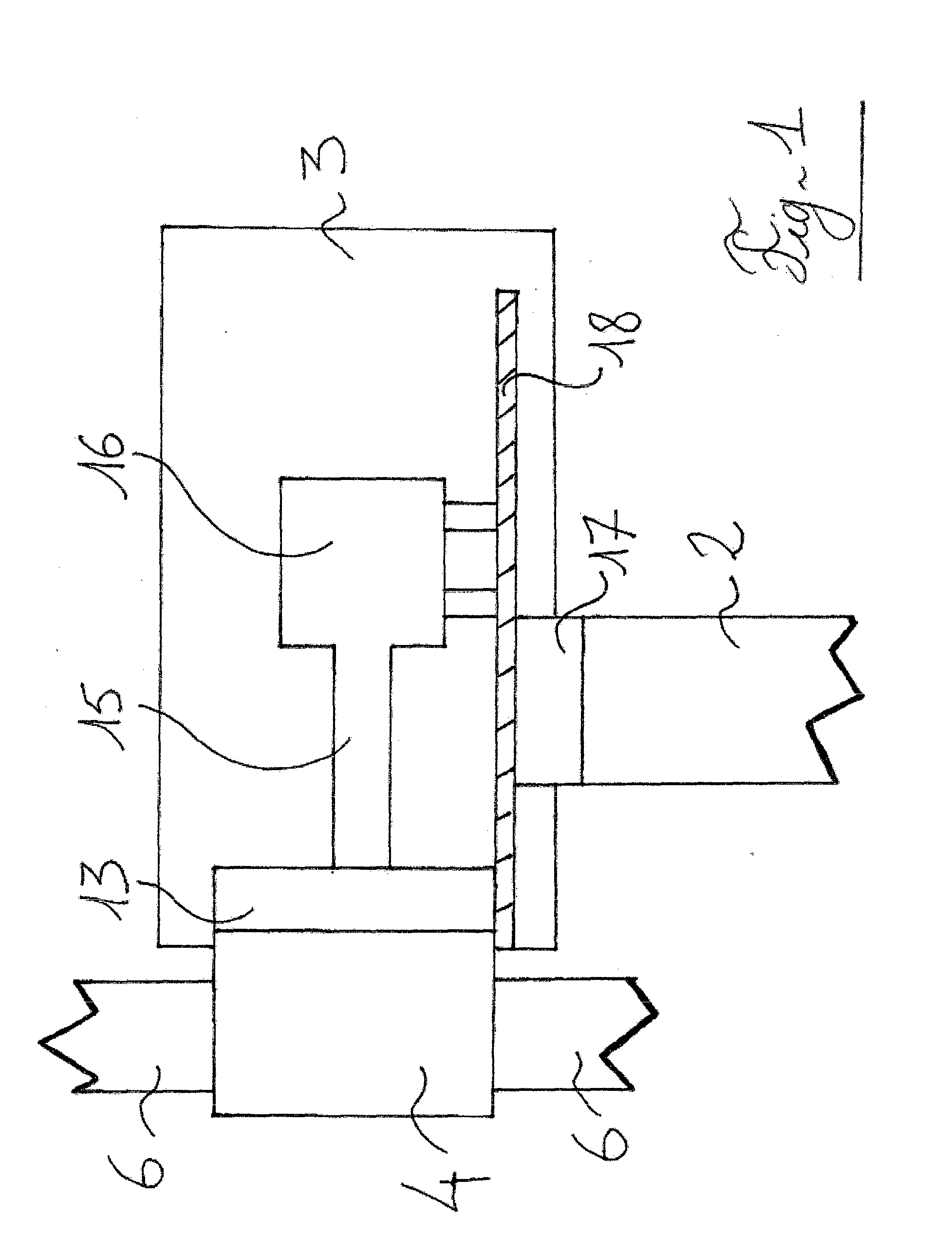
[0076]With reference to FIG. 1, a wind generator (1) of the prior art conventionally comprises one or several blade(s) (6) attached at equal distances from each other to a hub (4), this blade(s) (6)-hub (4) assembly forms the rotor, said rotor is connected to a power transmission system comprised of a low-speed shaft (not represented) connected to a multiplier (13) connected to a high-speed shaft (15), the power transmission system is connected to a generator (16) which produces electricity. The power transmission system and the generator (16) are housed on a support frame (18) itself housed ...


PUM


Abstract

A device making it possible considerably and remotely to reduce the diameter of the rotor of a wind generator (1) includes a connecting piece (5) connecting the blade (6) to the hub (4) of the wind generator (1), the central axes (B1-B2) of the respective ends (5.1-5.2) of which components form a certain angle (α), the end (5.1) is able to rotate about its central axis (B1) causing the blade (6) to pivot and once the blade has pivoted it is inclined toward the nacelle (3). When the blade (6) is inclined in this way, the connecting piece (5) and the rotor are immobilized, forming the position in which the wind generator (1) is protected. The device is intended to allow optimum and safe operation of the wind generators in regions subjected to violent winds.

Description

TECHNICAL FIELD[0001]The invention relates to the field of horizontal-axis wind generators, hereinafter referred to as “wind generators”, and particularly to a device and method for protecting a wind generator in the event of violent winds as well as a wind generator provided with such a device.[0002]The device according to the invention is particularly intended to allow the optimum and safe operation of wind generators in regions subject to violent winds, such as tropical cyclones. The principle of the present invention consists, in the event of violent winds, in significantly reducing the diameter of the blade rotor of the wind generator and then blocking said rotor to form a position for protecting the wind generator in the event of violent winds.[0003]The electricity production from the primary resource, which is the wind, allows to produce electricity without emitting greenhouse gas. In addition, this primary resource is free and renewable contrary to fossil resources. Finally,...

Claims


Application Information

Patent Timeline
IPC IPC(8): F03D7/02F03D9/00
CPCF03D7/022F03D7/0268F03D9/002F03D1/0658F05B2240/2022F05B2270/3201F03D9/25Y02E10/72F03D80/70F03D15/10
Inventor CUZENARD, PASCAL
Owner CUZENARD PASCAL
Why Eureka
Try Eureka