Apparatus and method for manufacturing microporous plastic film roll

a microporous plastic and apparatus technology, applied in the field of apparatus and a manufacturing method of microporous plastic film rolls, can solve the problems of limiting the dustproof effect, no direct improvement in productivity, and high risk, and achieve the effect of reducing the occurrence of pinhole faults

Inactive Publication Date: 2014-12-25
TORAY IND INC +1
View PDF19 Cites 9 Cited by
  • Summary
  • Abstract
  • Description
  • Claims
  • Application Information

AI Technical Summary

Benefits of technology

[0021]According to an embodiment of the present invention, a plastic film is conveyed so that a side of the plastic film opposite the side being in contact with the conveying rollers is in a noncontact state in a range being in contact with the conveying rollers, thereby eliminating a risk that sharp foreign bodies may stick in the conveying rollers and reducing the creation of pinholes by foreign bodies stuck in the surface of the conveying rollers as compared to a case of using a conventional nip roller. The present invention therefore has the effects of reducing the occurrence of pinhole faults and conveying the plastic film favorably.
[0022]When using the touch roller, the part of the touch roller to be in contact with the plastic film has a Vickers hardness

Problems solved by technology

Although the technology disclosed in Non Patent Literature 1 is effective to a certain extent for preventing shipment of products with pinholes found by inspection, it does not reduces pinholes themselves, resulting in no direct improvement in productivity.
Because the film manufacturing process has a long conveyance distance, downstream processes have a higher risk of causing pinholes by foreign bodies, thus limiting a dustproof effect despite strict management of dust proofing.
Because the surface of the conveying rollers disclosed in Patent Literature 1 is uniformly flat, a decrease in gripping force caused by air lubrication has induced unfavorable film meandering.
In particular, when air pe

Method used


Image

  • Apparatus and method for manufacturing microporous plastic film roll
  • Apparatus and method for manufacturing microporous plastic film roll
  • Apparatus and method for manufacturing microporous plastic film roll

Examples


example 1

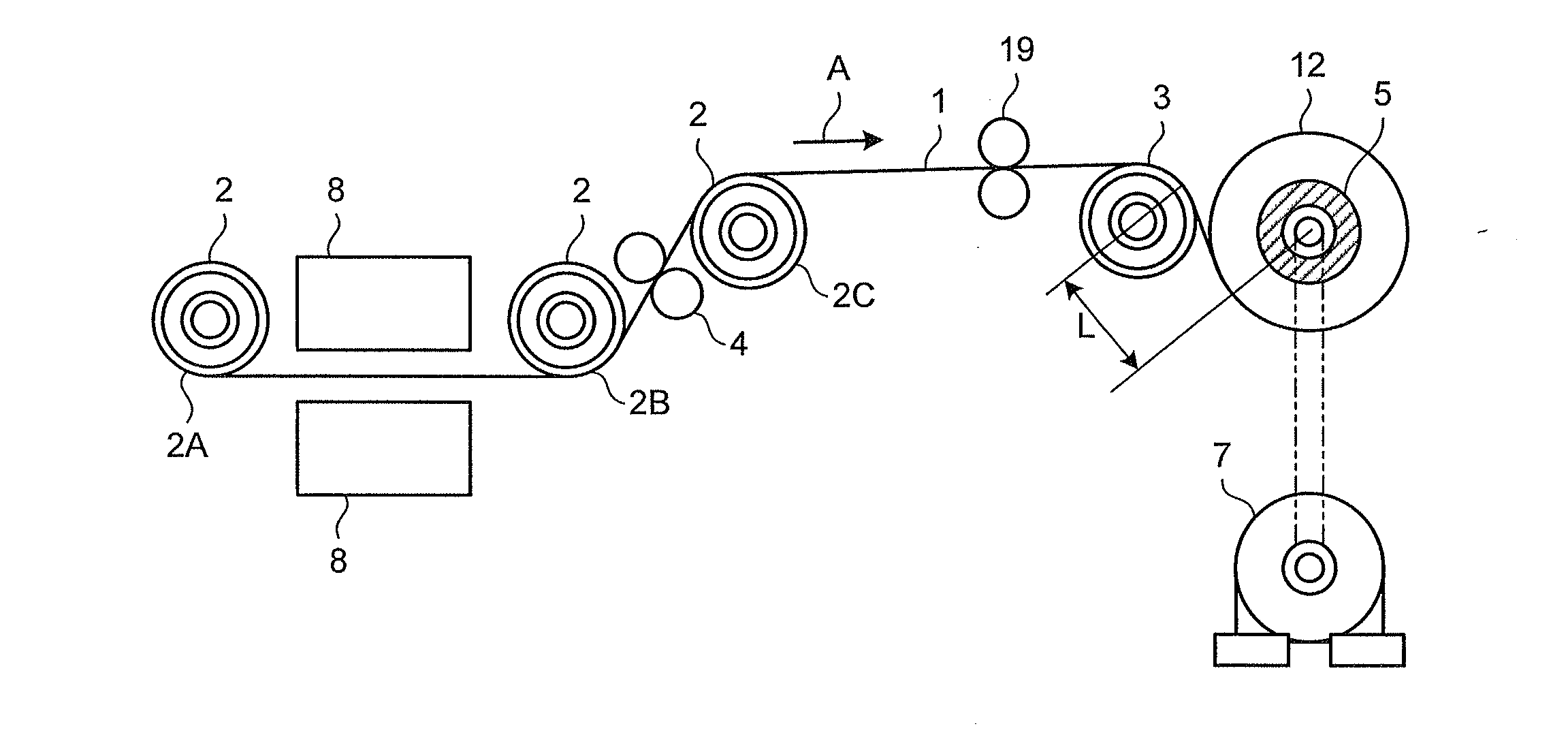
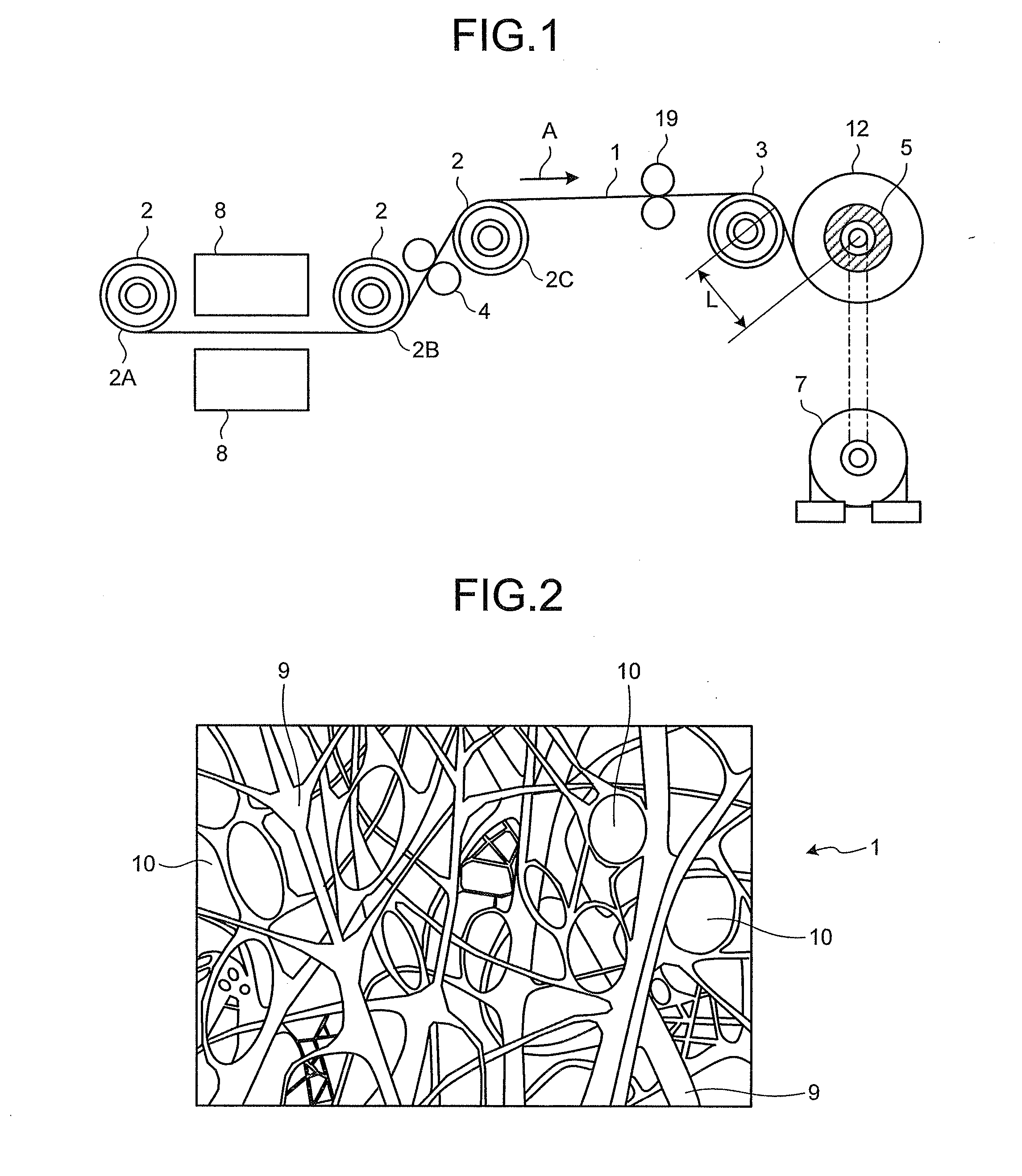
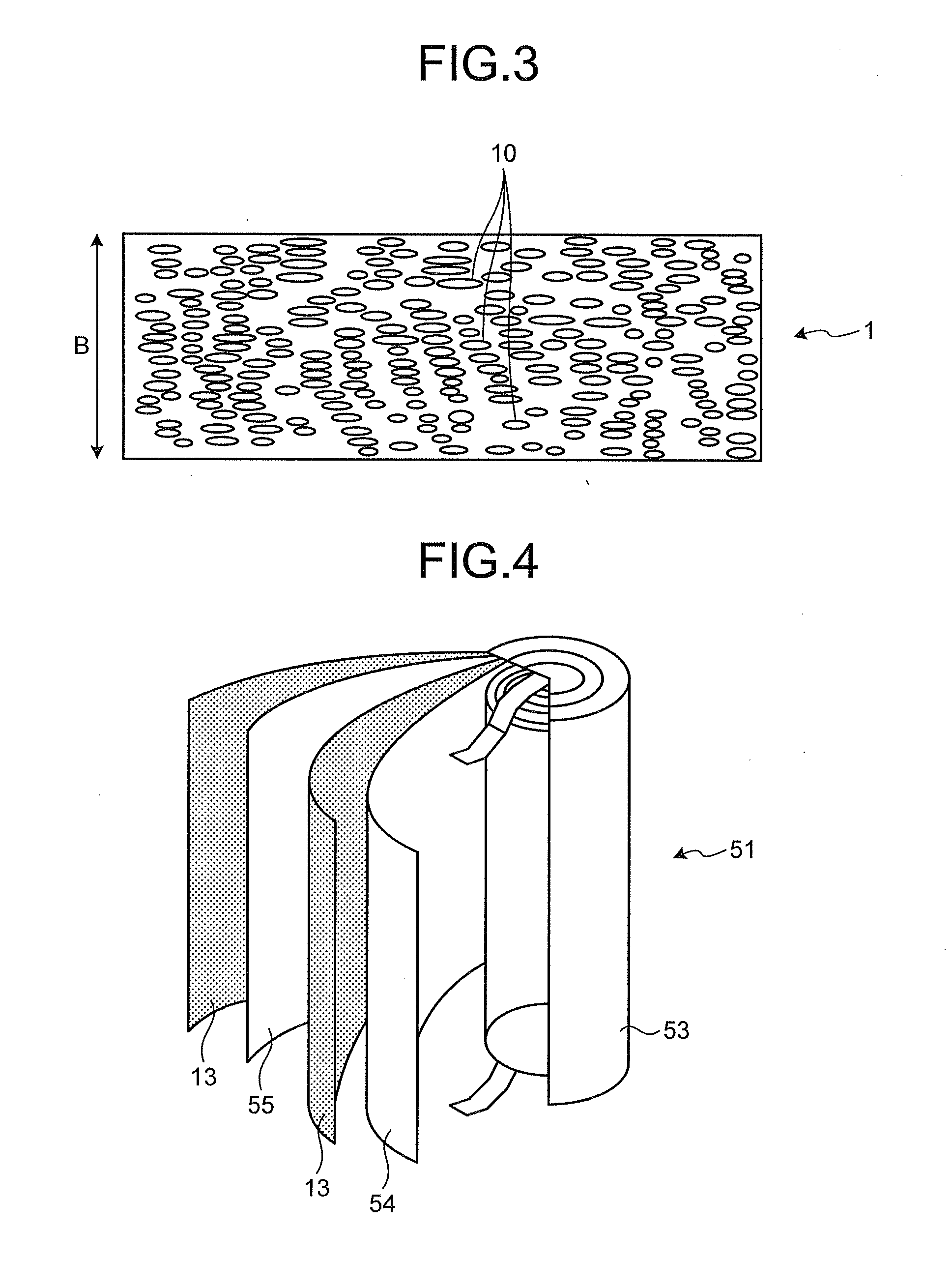
[0091]The polypropylene microporous plastic film 1 formed with through holes 10 as illustrated in FIG. 2 and FIG. 3 by a biaxial stretching process after controlling a crystal structure of polypropylene was conveyed by a conveyance system having the pinhole fault detector 8 as illustrated in FIG. 1 and was wound continuously on the winding core 5 to manufacture the microporous plastic film roll 12. The air permeability of the microporous plastic film 1 was measured while passing 100 ml of air using a B type Gurley tester stipulated in Japanese Industrial Standards JIS P8117 at a temperature of 23° C. and a humidity of 65%, and the result was 300 seconds. The cutting unit 4 of the shear-cutting type was arranged at some midpoint in the conveyance system to cut the microporous plastic film 1 into a width of 50 mm. The thickness of the microporous plastic film 1 was 30 μm.

[0092]Although not illustrated in FIG. 1, the conveying rollers 2 and the near roller 3 are all coupled to a belt a...

example 2

[0096]The material of the part of all the conveying rollers 2 including the conveying roller 2C and the near roller 3 to be in contact with the microporous plastic film 1 was metal made of hard chromium plating (hereinafter HCr). The Vickers hardness of the contact part of the near roller 3 was measured with a test load of 2 N based on Japanese Industrial Standards JIS Z2244, and the result was a value of 1,000. As for the surface roughness of the contact part (metallic surface) of the near roller 3, the arithmetic average roughness Ra was determined based on Japanese Industrial Standards JIS B0601 (2001) by a contact type surface roughness measurement machine manufactured by Mitutoyo Corporation with a probe material of diamond, a probe tip radius of 2 μm, and a measurement force of 0.75 mN, and the result was 0.9 The Vickers hardness of the HCr part was measured by a measurement method described in JIS 22244 (2009), and the result was 800. The wrinkle removing unit 19 illustrated ...

example 3

[0097]The same microporous plastic film 1 as Example 1 was wound by the conveyance system in FIG. 1 at the same speed and tension conditions. The conveying roller 2C had many grooves on its surface and was a suction roller with its inside sucked by a blower. The suction pressure was −5 kPa. The material of the other conveying rollers 2 and the near roller 3 was HCr, and its arithmetic average roughness Ra was 0.9 μm like Example 2. The combination of these conditions is listed in FIG. 11.


PUM

PropertyMeasurementUnit
Lengthaaaaaaaaaa
Lengthaaaaaaaaaa
Molar densityaaaaaaaaaa

Abstract

In an apparatus for manufacturing a microporous plastic film roll by conveying a microporous plastic film by conveying rollers and then winding the microporous plastic film in a roll shape while being brought close to a near roller or being brought into contact with a touch roller, a part of the touch roller to be in contact with the plastic film has a Vickers hardness of 100 to 2,000, and the microporous plastic film is conveyed so that a side of the microporous plastic film opposite the side being in contact with the conveying rollers is in a noncontact state in a range being in contact with the conveying rollers.

Description

CROSS REFERENCE TO RELATED APPLICATIONS[0001]This is the U.S. National Phase application of PCT / JP2012 / 083904, filed Dec. 27, 2012, which claims priority to Japanese Patent Application No. 2011-285999, filed Dec. 27, 2011, the disclosures of each of these applications being incorporated herein by reference in their entireties for all purposes.FIELD OF THE INVENTION[0002]The present invention relates to an apparatus and a method for manufacturing a microporous plastic film roll.BACKGROUND OF THE INVENTION[0003]There have often been cases where pinholes existing in various films cause quality problems. As described in Non Patent Literature 1, for example, because pinholes in food packaging films may cause troubles such as liquid leakage from contents, the Food Sanitation Law stipulates testing methods of sticking, friction, flex fatigue, and the like so as to prevent pinholes from being created during film manufacturing processes.[0004]Because pinholes in separators for film capacitor...

Claims


Application Information

Patent Timeline
IPC IPC(8): B29D99/00
CPCB29L2031/755B29D99/005B65H18/10B65H2404/19B65H2404/532B65H2701/175B65H23/195B65H18/26
Inventor ICHINOMIYA, TAKASHIIIZUKA, TAKANORIKANEKO, KENJI
Owner TORAY IND INC
Why Eureka
Try Eureka