Equipment and Methods for Downhole Surveying and Data Acquisition for a Drilling Operation

a technology for drilling operations and equipment, applied in the field of equipment and methods for drilling operations, can solve the problems of increasing the inventory of core orientation equipment, reducing the accuracy of drilling operations, and often unsealing of roads and wells, so as to reduce human error, increase efficiency, and fast and accurate rig status data acquisition

Active Publication Date: 2014-12-25
GLOBALTECH CORP PTY LTD
View PDF6 Cites 38 Cited by
  • Summary
  • Abstract
  • Description
  • Claims
  • Application Information

AI Technical Summary

Benefits of technology

[0027]One or more preferred forms of the present invention advantageously reduces complex operational methods prevalent at most drill rig sites, such as cumbersome handling and operation, incompatible equipment data outputs, and keeping track of multiple activity and events while operating the drill rig according to specified targets in a given time / cost budget.
[0028]At least one embodiment of the present invention provides a system incorporating reduced instrumentation component physical size(s) with the aid of component / module miniaturisation. This reduction in physical size of components allows for thicker wall pressure housings that enable component use in deep hole exploration / drilling.
[0029]Where preferred, use of composite materials may replace heavier brass and steel housings, making it possible to package pieces of equipment into one or more manageable (and preferably light weight) carrying cases. This adds the further advantage of lower shipment costs and portability, while being able to keep track of all components which fit into moulded receptacles in its carrying case. The instruments and hardware components in a system according to one or more embodiments of the present invention are built to be fully data and function compatible, so much so that a (preferably hand-held) control device is able to be used to initiate, interrogate and control all the survey / core-orientation instruments as well as log all drilling activity / events occurring at the rig.

Problems solved by technology

In remote areas suitable for mining and drilling operations, such roads are often unsealed and within harsh environmental conditions.
This process is time consuming and costly considering the high cost of the drill rig on-site and that this process is repeated every 3 or 6 metres of drilling.
This adds substantial weight to the core orientation equipment inventory.
This total assembly including the survey probe, its brass pressure barrel and three aluminium extension rods again adds substantial weight and considerable assembly / disassembly time to the survey process.
This can be a lengthy process with added care required not to damage the instrument during handling or being dropped in water or mud as would normally be the condition at a drill-rig site.
This additional data is not always available due to insufficient data recording at the drill rigs because of inaccessibility of the data or time constraints when drilling towards underground targets within a limited time.
The problems experienced from present operating methods comes from having to manually record data from the variety down-hole instruments source from various 3rd party suppliers, which may or may not have compatible formats, then transferring the data to the overall manual logging sheets or laptop as required for eventual recording and billing to customer.
This current method is prone to human error, possible data incompatibility and excessive time required to compile information which would require further re-compilation at head office to include other neighbouring drill-rig data and activity / events.
Time delays and inherent inaccuracies as a result of manual human data recording can cause delays in invoicing and receiving payment, and at worst, not charging for all items due to missing or poor recording methods.
A further inconvenience to the driller is the need to keep an inventory of third party core orientation / survey instruments, different manufacturer spare parts and related consumables such as batteries, long and cumbersome brass pressure barrels to protect survey instruments, sealing / waterproofing ‘O’ rings and grease to install associated pressure barrel housings before using the survey probes.

Method used


Image

  • Equipment and Methods for Downhole Surveying and Data Acquisition for a Drilling Operation
  • Equipment and Methods for Downhole Surveying and Data Acquisition for a Drilling Operation
  • Equipment and Methods for Downhole Surveying and Data Acquisition for a Drilling Operation

Examples


Embodiment Construction

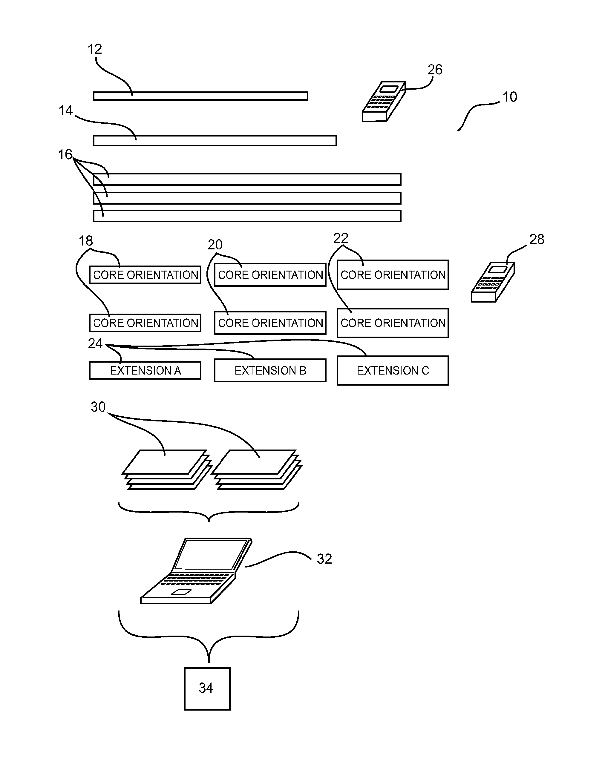
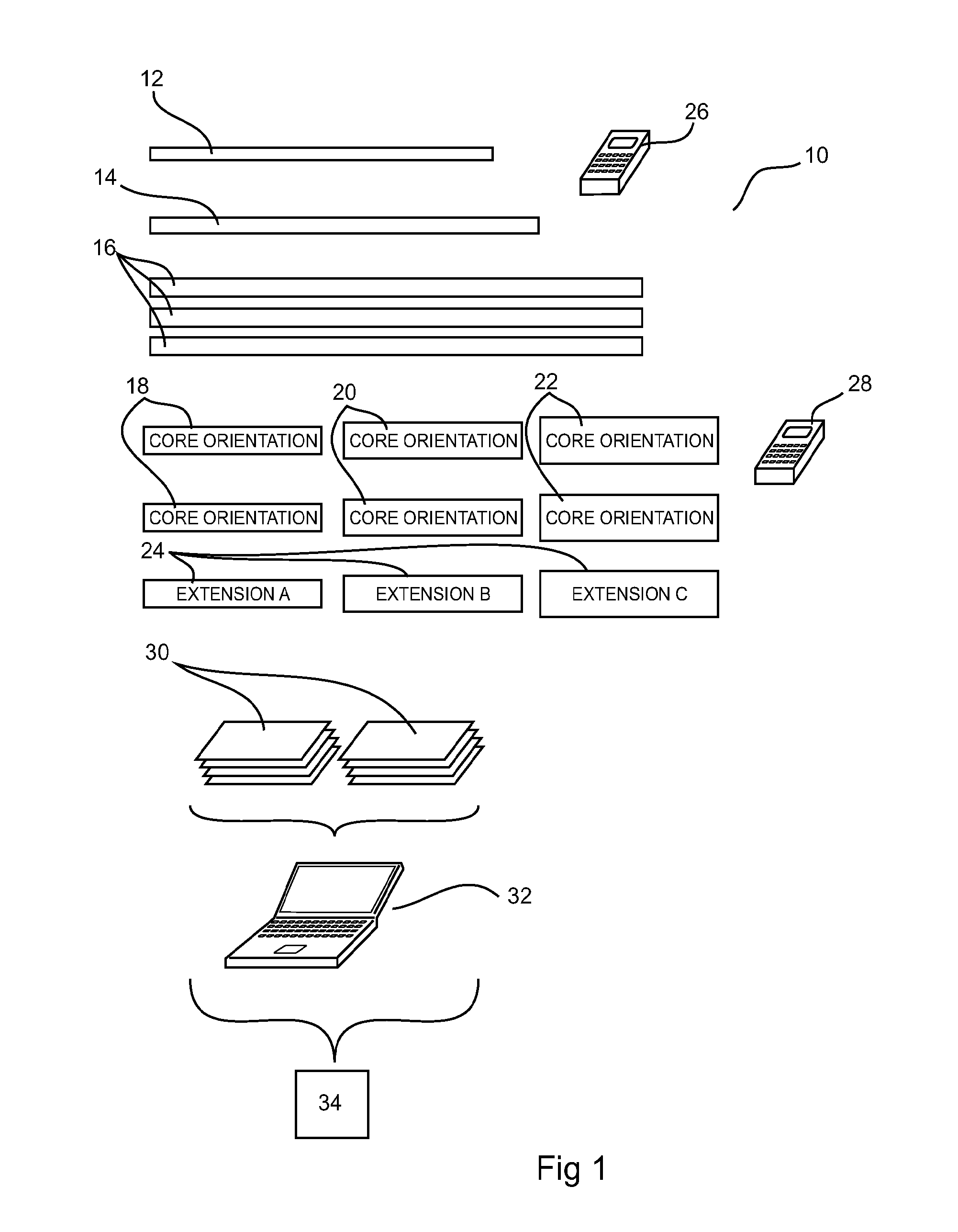
[0070]A known system 10 will first be described with reference to FIG. 1. FIG. 1 shows a comparison of currently required equipment to carry out surveying, core orientation using three sizes for varying drill hole diameters in deep hole drilling, and logging all events and activity at a drill-rig site.

[0071]Extracting Core Samples During Drilling

[0072]As with the description of known systems and components in the background section above, the common system 10 and method for core extraction and orientation requires a process of dismantling at least two assembly sections to complete the orientation. As every 3 m or 6 m requires core orientation, a significant amount of time is spent during this process. For deep hole drilling where at least three hole sizes are encountered, the equipment count (and weight) for core orientation equipment almost trebles (as seen in FIG. 1). This occurs because a relatively wide borehole can first be drilled. As friction increases with depth, a narrower ...


PUM


Abstract

An adaptor (64,66) has attachment means to releasably attach a core orientation instrument (60) or survey probe to a drill string component and / or drill string, preferably by one or more screw threads (70, 72, 76, 78), retaining screws, bolts, clips or pins or welding / soldering. Anti release means, such as a circlip, can be used to prevent release of the adaptor. A survey system for obtaining data from a drilling operation includes a core orientation instrument, a downhole survey probe and a common single remote controller / data logger configured to control or communicate with both the survey probe and the core orientation instrument. Further, a survey system includes multiple components arranged in a portable container for transport and deployment at a drilling site include a survey probe, a core orientation instrument and a single controller configured to control or communicate with the survey probe and core orientation instrument.

Description

FIELD OF THE INVENTION[0001]The present invention relates to equipment, system and methods for improved downhole surveying and data acquisition at a drill site, such as for obtaining a core orientation sample and handling data relating to the sample.BACKGROUND TO THE INVENTION[0002]Drillers contracted by mining companies are required to drill numbers of exploratory subsurface drill holes at a chosen mine site to extract underground core samples in order to determine locations of mineralisation and the feasibility to proceed with mineral extraction.[0003]Such operations extract a core during drilling (in ‘diamond drill-bit drilling’ the bit has a centre hole which allows the core sample to enter through during drilling). Core lengths are variable, but usually between 3 m and 6 m lengths and are extracted progressively for the entire hole.[0004]Each extracted core sample is marked for its orientation position before extraction, with additional survey data of that cores position such a...

Claims


Application Information

Patent Timeline
Patent Type & Authority Applications(United States)
IPC IPC(8): E21B47/01E21B47/024E21B47/12
CPCE21B47/01E21B47/024E21B47/12E21B25/16
Inventor WILKINSON, BRETT JAMESKLASS, MICHAEL ALANANWAR, JOHANHEJLEH, KHALEDSTEWART, GORDON
Owner GLOBALTECH CORP PTY LTD
Why Eureka
Try Eureka