
Multi-vehicle model collinear flexible framing system

a flexible framing and multi-vehicle technology, applied in the field of consolidation stations, can solve the problems of high building cost and meet the production requirements of domestic automobile factories very well, and achieve the effects of high production efficiency, wide applicability and fast pa

Active Publication Date: 2015-01-01
GUANGZHOU MINO AUTOMOTIVE EQUIP CO LTD
View PDF8 Cites 28 Cited by
  • Summary
  • Abstract
  • Description
  • Claims
  • Application Information

AI Technical Summary

Benefits of technology

The present invention aims to provide a multi-vehicle type co-production line flexible framing with high production efficiency, a fast pace, a wide applicability, and a flexible and convenient use, to meet the requirements for the automatic welding production of the automobile body in white. It achieves this by significantly increasing the number of welding robots that can be used and improving the utilization of the framing station. The present system also reduces the switching time and increases the capacity of the production line. Additionally, the present invention has a compact structure and is cost-effective.

Problems solved by technology

Domestic enterprises have a weak competitive power in this filed, even though there are some defects in several foreign flexible framing solutions, such as a large floor area, a slow production beat, incapability of switching with the line, restrictions on the co-production line vehicle types, or a high building cost, and it cannot satisfy the production requirement of the domestic automobile factories very well, and brings a large impact to the progress of our automobile production industry.

Method used


Image

  • Multi-vehicle model collinear flexible framing system
  • Multi-vehicle model collinear flexible framing system
  • Multi-vehicle model collinear flexible framing system

Examples


Embodiment Construction

[0025]The present invention is further described in detail below in connection with the accompanying drawings:

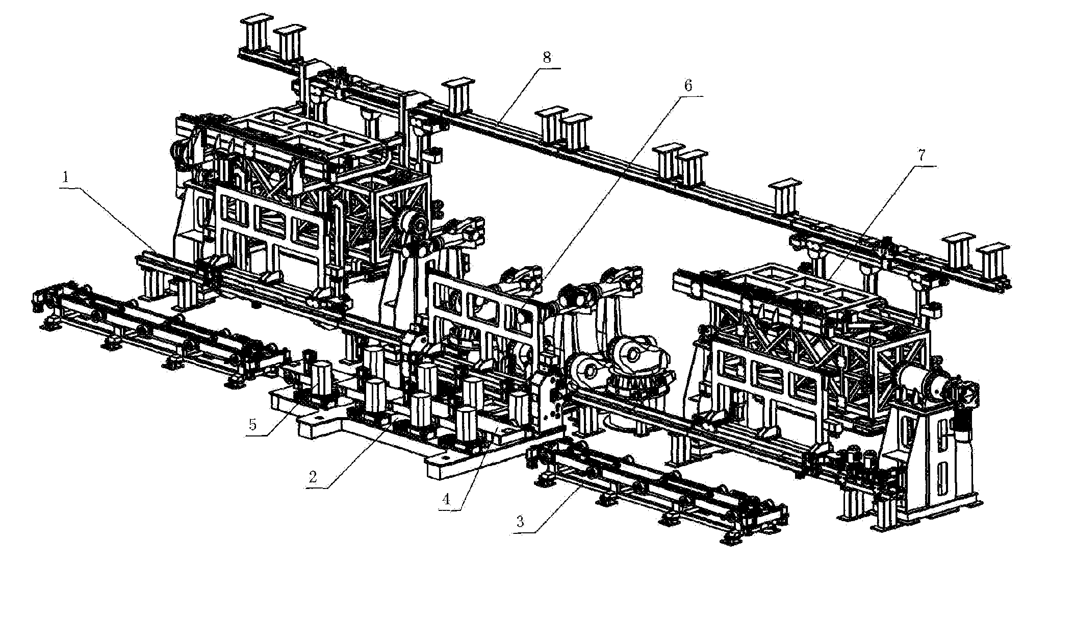
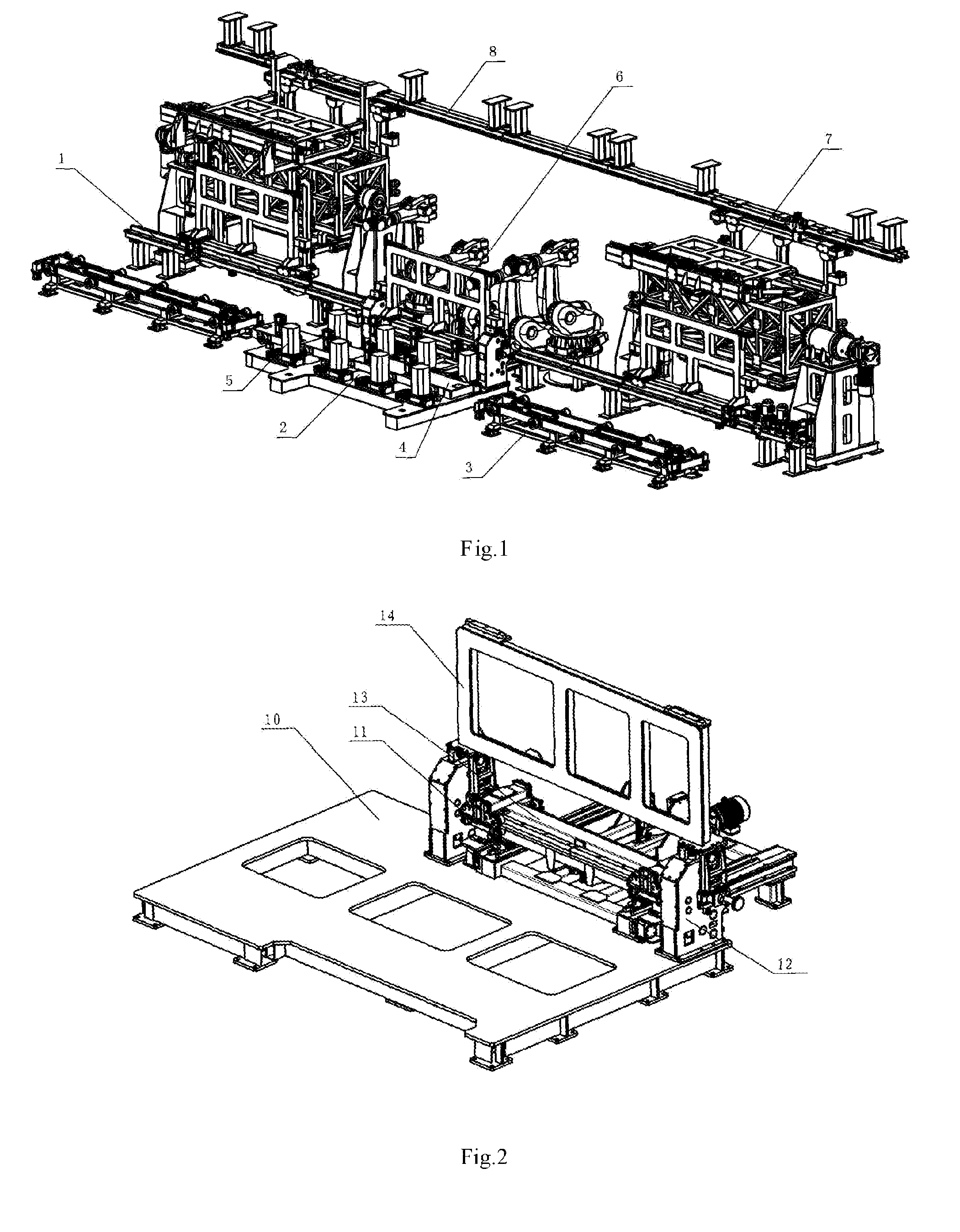
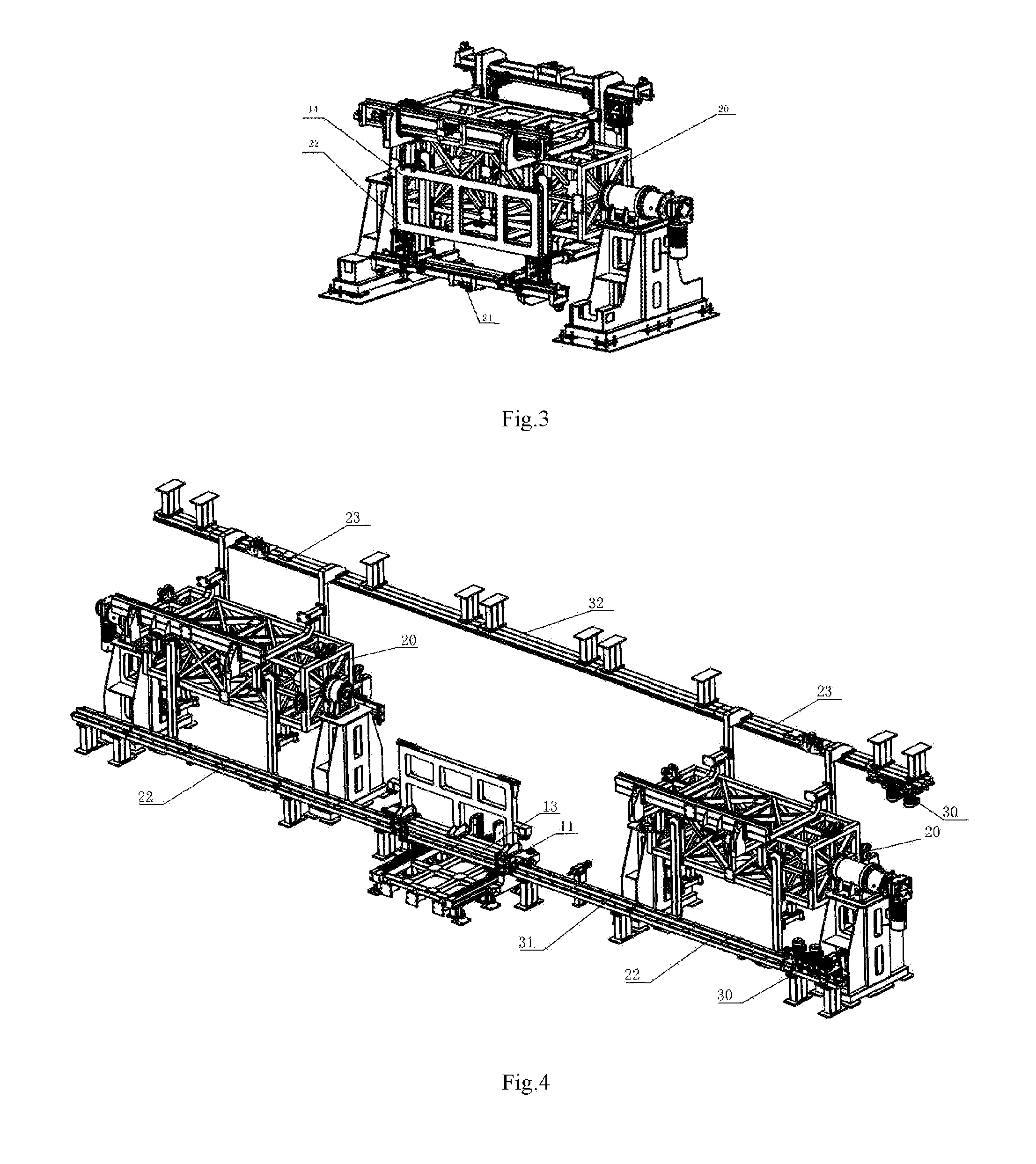
[0026]As shown in FIG. 1, a multi-vehicle type co-production line flexible framing described by the present invention comprises a robot welding system, a high speed transport system 3, a floor panel intelligent flexible positioning system 2, and a side panel flexible positioning and switching system 1. The robot welding system is used for welding the positioned vehicle body, and is the last execution mechanism of the procedure; the high speed transport system 3 is responsible for transferring the automobile body in white, in order to automatically enter the next procedure from the previous one; the floor panel intelligent flexible positioning system 2 cooperates with the high speed transport system 3, and is responsible for positioning and fixing the floor panel of body, in order to process the floor panel of body in a flow operation; the side panel flexible positioning and ...


PUM

PropertyMeasurementUnit
Flexibilityaaaaaaaaaa
Speedaaaaaaaaaa

Abstract

A multi-vehicle type co-production line flexible framing is disclosed, comprising a robot welding system, a high speed transport system, a floor panel intelligent flexible positioning system, and a side panel flexible positioning and switching system. The floor panel intelligent flexible positioning system is correspondingly connected to a transfer rail of the high speed transport system. The side panel flexible positioning and switching system comprises a side panel fixture consolidation system, a fixture storage system, and a fixture switching and rail system. The side panel fixture consolidation system corresponds to the side of the floor panel intelligent flexible positioning system. The fixture storage system is arranged on two sides of the side panel fixture consolidation system in the transfer direction of the high speed transport system. The fixture switching and rail system is connected between the side panel fixture consolidation system and the fixture storage system. The improved structure is relatively compact and practical, has a short switching time, a high production efficiency, and a small floor area, and may use a large number of welding robots, fully satisfying the capacity requirement of 60JPH of the automobile factory.

Description

FIELD OF THE INVENTION[0001]The present invention relates to a consolidation station on a production line of welding the automobile body in white, and in particular, relates to a multi-vehicle type co-production line flexible framing suitable for multiple vehicle types to use in common, belonging to the field of automobile manufacturing equipment.BACKGROUND OF THE INVENTION[0002]The future automobile is developing in the trend of many varieties, small batch, and high capacity. According to this trend, it is impractical to establish a new production line for each vehicle type, so producing multiple vehicle types simultaneously on one production line is the trend of future automobile equipment industry. The multi-vehicle type co-production line flexible framing may accomplish the welding of the floor assembly, the left side panel assembly, the right side panel assembly, and the roof assembly of the body in white, and is the core equipment on the automobile body in white flexible produ...

Claims


Application Information

Patent Timeline
IPC IPC(8): B65G35/00B23K37/04B62D65/02
CPCB62D65/022B23K37/04B62D65/024B65G35/00
Inventor YAO, WEIBINGSUN, PETER CHIHCHENGYANG, MENGHE, WEIHE, YIZHOU, KAIHUANG, HAI
Owner GUANGZHOU MINO AUTOMOTIVE EQUIP CO LTD
Learn More