Efficient electric machine

a technology of electric machines and electric motors, applied in the field of electrotechnology, can solve the problems of reducing the performance and power density of the machine, demagnetizing the permanent magnet, and requiring long service life and high reliability, so as to improve the efficiency of the electrical machine, improve the efficiency of the machine, and keep the magnetic gap small.

Active Publication Date: 2015-01-01
BROSE FAHRZEUGTEILE GMBH & CO KG HALLSTADT (DE)
View PDF8 Cites 27 Cited by
  • Summary
  • Abstract
  • Description
  • Claims
  • Application Information

AI Technical Summary

Benefits of technology

[0010]It is therefore an object of the invention to provide an electrical machine, which is inexpensive to manufacture, on the one hand, and is to be made stable and reliable to operate. In addition, the machine should have a high demagnetization resistance at a high achievable power density.
[0045]The permanent magnets of the third set, for example, in a spoke-like arrangement, constructed symmetrically around the rotor axis of the rotor, of the permanent magnets of the first and second set are advantageously symmetrically arranged between the spokes, or in V-shaped designs of pairs of permanent magnets or permanent magnet groups, the permanent magnets of the third set can be arranged in each case centrally between the legs of the V form. The material composition of the permanent magnets of the third set differs from the composition of the permanent magnets / composite bodies of the first and second set, whereby the composition of the first and second set can also be the same among each other. The magnetization direction of the permanent magnets of the third set is advantageously rotated within the cross-sectional plane of the rotor through an angle range between 60° and 120° to the magnetization direction of the permanent magnets of the first and second group, advantageously oriented perpendicular to the magnetization direction of the permanent magnets of the first and second group and / or in the radial direction of the rotor body. In this way, the permanent magnets of the third set can optimize the design of the magnetic flow pattern in the rotor body and thereby further increase the power density of the electric machine and / or contribute to the formation of a Halbach array.

Problems solved by technology

In addition, a long service life and high reliability are required.
Undesirable magnetic fields can arise in this case, for example, by self-induction, which can lead to demagnetization of the permanent magnets, particularly at higher operating temperatures.
This consequently leads to a reduction of the performance and power density of the machine.
However, these materials are rare and cost-intensive.

Method used


Image

  • Efficient electric machine
  • Efficient electric machine
  • Efficient electric machine

Examples


Embodiment Construction

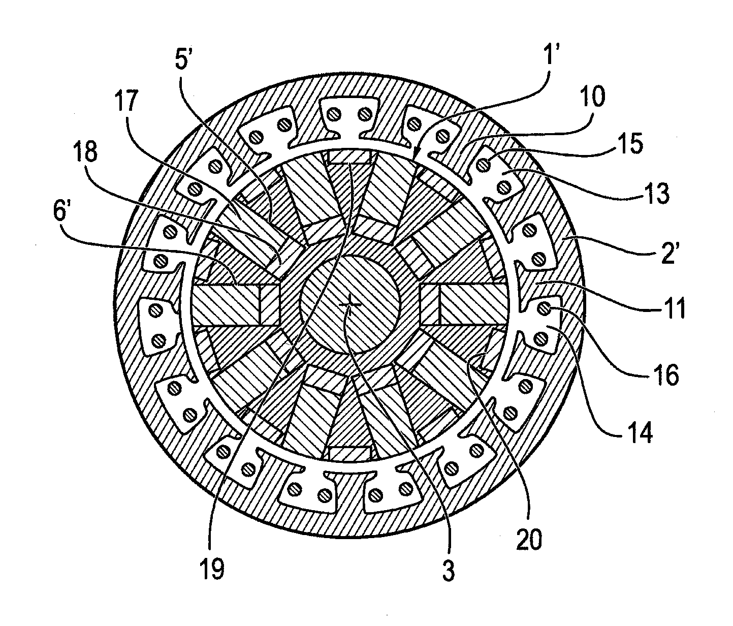
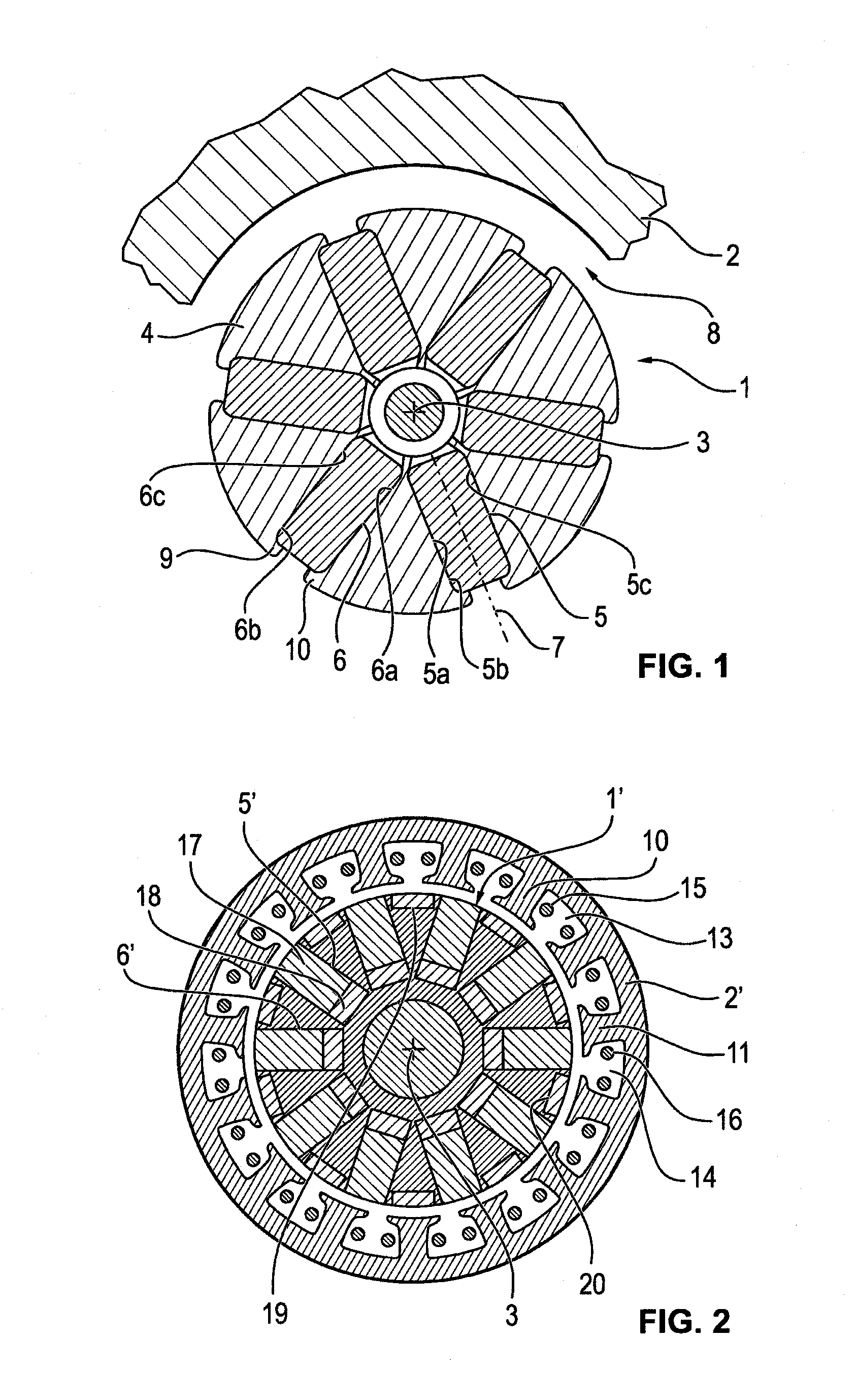
[0066]FIG. 1 shows a rotor 1 of an electric motor, which is mounted rotatably within a stator 2 around a rotor axis 3. It can be seen in the cross section of FIG. 1 that six permanent magnets 5, 6 are retained in receptacles 5a, 6a within rotor body 4, whereby longitudinal axes 7 of the receptacles are oriented radially with respect to rotor axis 3. This type of construction is a so-called spoke-shaped arrangement of the permanent magnets. Magnetic gap 8 is illustrated as excessively large in FIG. 1. It is formed between the stator and the cylindrical outer surface of rotor 1.

[0067]In order to achieve an especially high efficiency of a corresponding electric motor, efforts are made to design magnetic gap 8 / rotor gap as small as possible.

[0068]Permanent magnets 5, 6 do not quite reach the cylindrical outer surface of rotor 1, because they are retained in the receptacles by projections 9, 10 of the rotor body in the area of the radially outer part of receptacles 5a, 6a. In particular,...


PUM


Abstract

An electric machine having a stator and a rotor which is mounted so as to be rotatable about a rotor axis and has a rotor body, in which at least two permanent magnets are arranged in receptacles, a first of which component magnets is associated with a first set of permanent magnets, and a second of which component magnets is associated with a second set of permanent magnets. The permanent magnets of the first set differ from the permanent magnets of the second set with respect to the material composition, In particular to the magnetic properties, and wherein at least one permanent magnet of the first or second set or at least one composite body has a contour, the cross-sectional face of which, being located perpendicularly with respect to the longitudinal axis, decreases within the respective receptacle towards that end thereof which is radially further to the outside.

Description

[0001]This nonprovisional application is a continuation of International Application No. PCT / EP2013 / 000741, which was filed on Mar. 13, 2013, and which claims priority to German Patent Application No. 10 2012 005 141.7, which was filed in Germany on Mar. 13, 2012, German Patent Application No. 10 2012 020 927.4, which was filed in Germany on Oct. 25, 2012, International Patent Application No. PCT / EP2012 / 004460, which was filed on Oct. 25, 2012, International Patent Application No. PCT / EP2012 / 004461, which was filed on Oct. 25, 2012, and International Patent Application No. PCT / EP2012 / 004462, which was filed on Oct. 25, 2012 and which are all herein incorporated by reference.BACKGROUND OF THE INVENTION[0002]1. Field of the Invention[0003]The invention relates to the field of electrotechnology and relates particularly to rotating electrical machines, therefore, for example, electric motors or generators.[0004]2. Description of the Background Art[0005]Particularly in automotive technol...

Claims


Application Information

Patent Timeline
Patent Type & Authority Applications(United States)
IPC IPC(8): H02K1/02H02K1/27
CPCH02K1/02H02K1/2773H02K1/27H02K2201/03H02K2213/03H02K1/276H02K1/06H02K3/46H02K1/2766H02K21/16H02K1/17
Inventor ZHANG, SUNNYFIEDERLING, DANIELBAUMGARTNER, JOACHIMXU, JIN
Owner BROSE FAHRZEUGTEILE GMBH & CO KG HALLSTADT (DE)
Why Eureka
Try Eureka