Chip-scale star tracker

Active Publication Date: 2015-01-01
CHARLES STARK DRAPER LABORATORY
View PDF5 Cites 14 Cited by
  • Summary
  • Abstract
  • Description
  • Claims
  • Application Information

AI Technical Summary

Benefits of technology

[0002]Aspects and embodiments are directed to a miniaturized star tracker (also referred to as a star camera) in which traditional optics are replaced with a wafer-based structures, providing a system that has a large light collection aperture on a wafer-thin substrate. This combination may enable conformal mounting on a spacecraft or other vehicle. According to certain embodiments, and as

Problems solved by technology

Thus, traditional star trackers are

Method used


Image

  • Chip-scale star tracker
  • Chip-scale star tracker
  • Chip-scale star tracker

Examples


Embodiment Construction

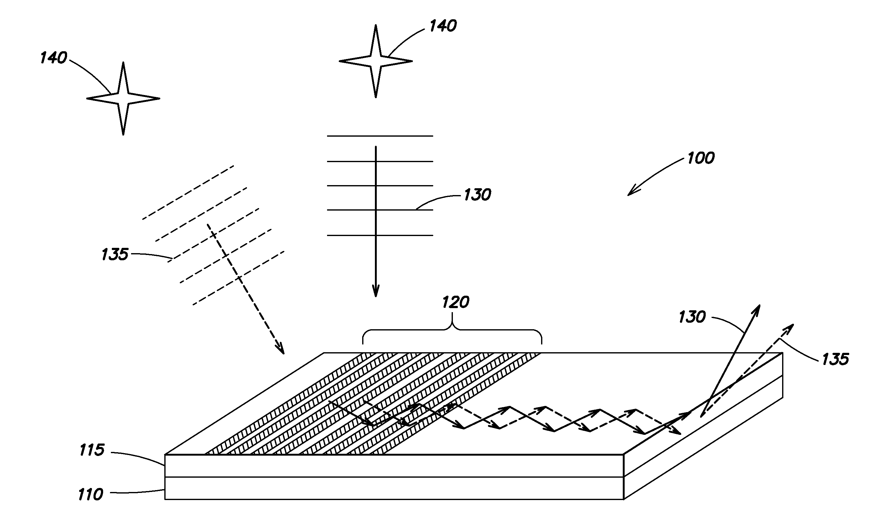
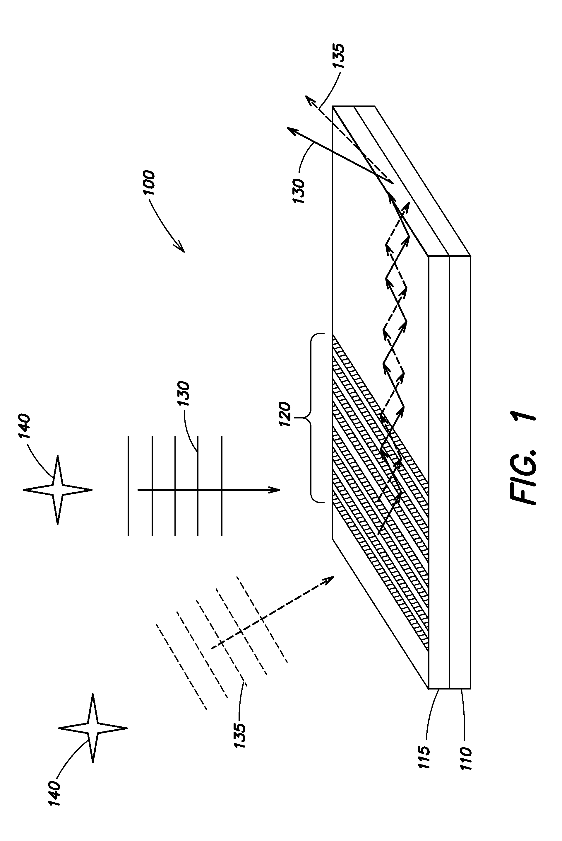
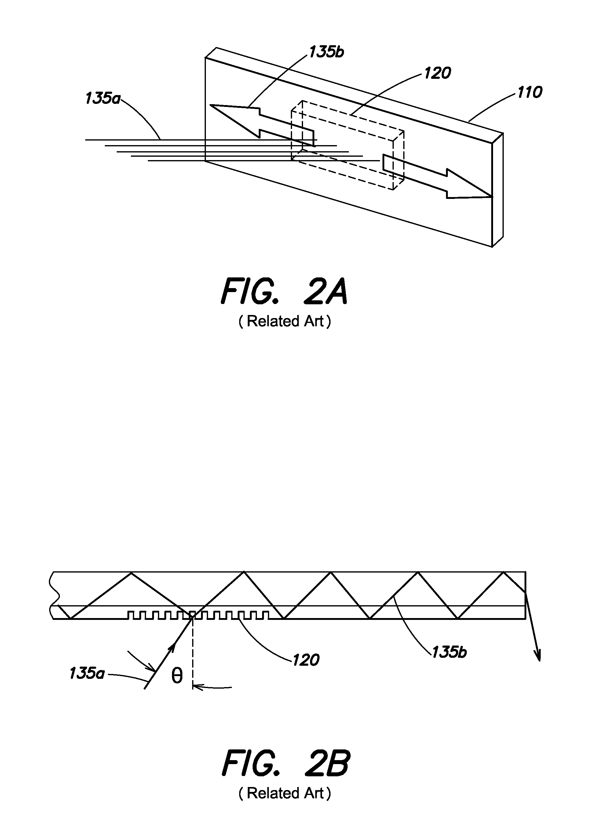
[0021]As discussed above, traditional star trackers are typically large due to the need for a large optical aperture to achieve sufficiently high resolution imaging, which generally results in the system having a large focal (and physical) length. However, in many applications it may be desirable to minimize the size and weight of the star tracker system. In a chip-scale star tracker system according to aspects and embodiments of the present invention, focal length has no meaning because the light is not imaged as in a traditional lens or minor based system, but is instead coupled and filtered into a planar light-guide structure patterned on a layered wafer substrate. The captured light propagates within the wafer material and is detected at the edges of the wafer with low noise photo-detectors. The detected light is analyzed to obtain the detailed propagation characteristics which determine the star angle, as discussed further below. Thus, aspects and embodiments are directed to a ...


PUM


Abstract

A chip scale star tracker that captures plane-wave starlight propagating in free space with a wafer-thin angle-sensitive broadband filter-aperture, and directs the light into a waveguide structure for readout. Angular information about the star source is determined from characteristics of the starlight propagating in the waveguide. Certain examples include internal propagation-constant-based baffling to elimination stray light from extreme angles.

Description

BACKGROUND[0001]Traditional star trackers are high-performance imaging instruments that contain the optical and processing elements typically found in camera systems, such as an imaging sensor focal plane and a telescope. For far-field imaging, the diffraction equation establishes a direct relationship between maximum object angular resolution (and thus imaging performance) and the diameter of the optical aperture. Accordingly, the telescope of a star tracker must generally have a fairly large aperture diameter in order to collect a sufficient amount of starlight to achieve reasonable imaging performance. As a result, the focal length (and physical length) of the telescope must be substantial as well. Thus, traditional star trackers are typically large in size, and bulky.SUMMARY OF INVENTION[0002]Aspects and embodiments are directed to a miniaturized star tracker (also referred to as a star camera) in which traditional optics are replaced with a wafer-based structures, providing a s...

Claims


Application Information

Patent Timeline
IPC IPC(8): G01C21/02
CPCG01C21/025G01B2290/10G01S3/7867G02B6/34G01S3/785G02B6/0288G01B9/06G02B6/124G02B6/122G02B6/262G02B6/3548G02B2006/12147
Inventor LAINE, JUHA-PEKKABLASCHE, GREGORY P.CHAPARALA, MURALI V.DAWSON, ROBINLANE, BENJAMINSMITH, STEPHEN P.WALDRON, ERIK
Owner CHARLES STARK DRAPER LABORATORY
Why Eureka
Try Eureka