Flexible printed wiring board, flexible circuit board, and electronic apparatus using the flexible circuit board

a flexible circuit board and printed wiring technology, applied in the direction of laminating printed circuit boards, fixed installation, lighting and heating apparatus, etc., can solve the problems of increasing assembly man-hours, affecting size or product design, and insufficient rigidity, etc., to achieve convenient form

Inactive Publication Date: 2015-01-01
CANON COMPONENTS INC
View PDF6 Cites 82 Cited by
  • Summary
  • Abstract
  • Description
  • Claims
  • Application Information

AI Technical Summary

Benefits of technology

[0013]In view of the circumstances, an object of the present invention is to provide a flexible printed wiring board with excellent heat radiation that can easily form a three-dimensional shape by bending, a flexible circuit board, and an electronic apparatus provided with the flexible circuit board.

Problems solved by technology

The flexible printed board includes a copper foil pattern integrated with an insulating resin film, and the rigidity is not sufficient.
However, the configurations described in Patent Documents 1 to 3 require many members, and the increase in the number of components increases assembly man-hours.
Furthermore, the size or the product design may be affected in an electronic apparatus provided with the printed circuit board.

Method used


Image

  • Flexible printed wiring board, flexible circuit board, and electronic apparatus using the flexible circuit board
  • Flexible printed wiring board, flexible circuit board, and electronic apparatus using the flexible circuit board
  • Flexible printed wiring board, flexible circuit board, and electronic apparatus using the flexible circuit board

Examples


first embodiment

>

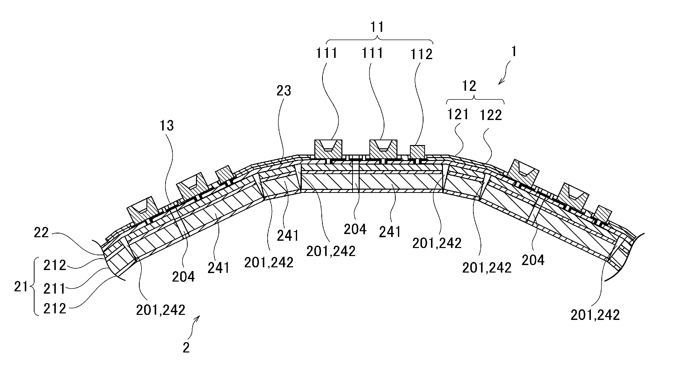
[0039]In a flexible circuit board 1 according to a first embodiment, electronic components 11, such as semiconductor devices and passive elements, are mounted on an FPC 2 (flexible printed wiring board: Flexible Print Circuit) for TAB (Tape Automated Bonding). The flexible circuit board 1 can hold a three-dimensional shape formed by bending the FPC 2, in a state that the electronic components 11 are mounted on the FPC 2. Alternatively, the flexible circuit board 1 is incorporated into another electronic apparatus, such as an illumination apparatus (described later), and used. In the first embodiment, a base film 21 of the FPC 2 applied to the flexible circuit board 1 has a function of heat radiation of the mounted electronic components 11 and the like.

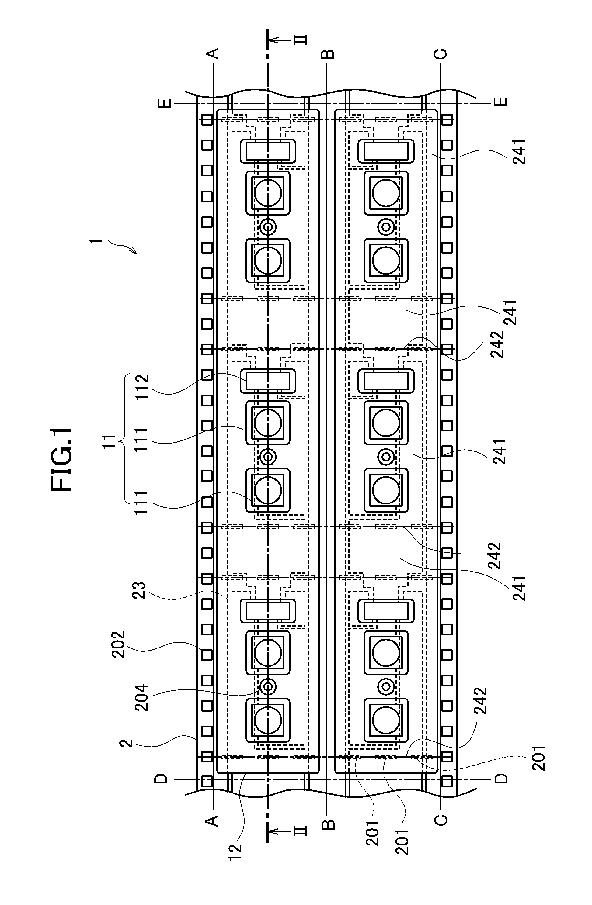
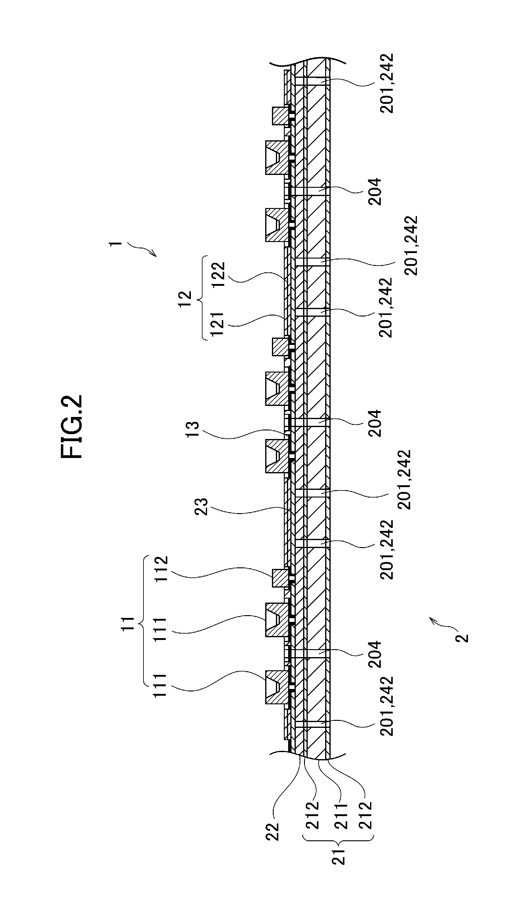
[0040]Configurations of the FPC 2 and the flexible circuit board 1 provided with the FPC 2 will be described with reference to FIGS. 1 and 2. FIG. 1 is a flat-surface schematic view showing an example of the configuration of the flexi...

first example

[0070]A first example of an electronic apparatus provided with the flexible circuit board 1 will be described. An illumination apparatus 5 will be illustrated in the first example of the electronic apparatus. FIG. 6 is a sectional schematic view showing a configuration of the illumination apparatus 5 in the first example of the electronic apparatus. The illumination apparatus 5 illustrated in this example includes a plurality of LEDs 111 as light emitting elements and can generate diffusive light. The illumination apparatus 5 includes the flexible circuit board 1 and a supporting member 51 on which the flexible circuit board 1 is attached. Although the illumination apparatus 5 can further include members such as a housing, this will not be illustrated and described here.

[0071]Rows of slit holes 201 are formed at the bending positions 242 of the FPC 2 (flexible circuit board 1), in series in the short direction like perforations. The rows of slit holes 201 are formed in the longitudi...

second example

[0075]A second example of the electronic apparatus provided with the flexible circuit board 1 will be described. The second example is an example of forming the flexible circuit board 1 in a three-dimensional shape to cause the FPC 2 to function as a housing of the electronic apparatus. An imaging apparatus 6 (digital camera) incorporated into a capsule endoscope will be illustrated in the second example of the electronic apparatus. FIG. 7 is a perspective view showing an example of a configuration of the imaging apparatus 6. As shown in FIG. 7, the FPC 2 (flexible circuit board 1) is formed in a bottomed square cylinder shape as an example of the three-dimensional shape. In FIG. 7, the near side is an open side of the square cylinder, and the far side is a bottom side of the square cylinder. Desired electronic components 11, such as a camera module 61 and LEDs 111 as light emitting elements, are disposed inside of the square cylinder. According to the configuration, the FPC 2 funct...


PUM


Abstract

An FPC includes: a base film including a first metal sheet; a first adhesive layer laminated on one of surfaces of the base film; and a conductor pattern bonded by the first adhesive layer; wherein a plurality of planar portions held in a planar shape and bending portions to be bent provided between the planar portions are arranged in a longitudinal direction, and the conductor pattern is covered by a metal support cover film including a second metal sheet and a second adhesive layer at the planar portions and is covered by a solder resist at the bending portions.

Description

CROSS-REFERENCE TO RELATED APPLICATIONS[0001]This application is based upon and claims the benefit of priority of the prior Japanese Patent Application No. 2013-135259, filed on Jun. 27, 2013, and the Japanese Patent Application No. 2014-129265, filed on Jun. 24, 2014, the entire contents of which are incorporated herein by reference.BACKGROUND OF THE INVENTION[0002]1. Field of the Invention[0003]The present invention relates to a flexible printed wiring board, a flexible circuit board, and an electronic apparatus using the flexible circuit board. Particularly, the present invention relates to a flexible printed wiring board including a base film including a metal sheet, a flexible circuit board in which electronic components are mounted on the flexible printed wiring board, and an electronic apparatus provided with the flexible circuit board.[0004]2. Description of the Related Art[0005]Conventionally, there is an illumination apparatus on which a solid-state light emitting element ...

Claims


Application Information

Patent Timeline
Patent Type & Authority Applications(United States)
IPC IPC(8): H05K1/02F21K99/00
CPCH05K1/028F21K9/30H05K1/0209H05K1/056F21S48/212F21S48/215F21S48/218F21Y2101/02H05K3/0058H05K2201/056H05K2201/10106H05K2201/10409F21Y2115/10F21S43/195F21S43/14F21S43/15H05K1/0278
Inventor UEHARA, HIROHARU
Owner CANON COMPONENTS INC
Why Eureka
Try Eureka